PART 2 of 3 – Fuels, Setting, Adjustment & Testing
FUELS
The combustion process of converting fuel to energy, not as popular as the international push toward carbon neutrality and emission reduction, still remain a vital force in producing steam and hot water via conventional and hybrid burners. Common fuels such as natural gas & propane come standard on most new boiler/burner systems. Alternate fuels such as bio-fuels, land-fill gas, methane from waste treatment facilities and ethanol from corn can be burned as primary, secondary or simultaneous fired configurations in some conventional boilers. Bio-mass fuels such as wood pellets, briquettes or logs and other raw materials are also used to fuel boilers. Gas fired boiler/burners, light fuel oils such as kerosene, #2 fuel oil and in some cases heavier oils which must be heated prior to use are often used as a reliable back-up fuel source. The above alternative liquid fuels come with more stringent regulation. They are most notably selected as back-up fuel at critical care facilities such as hospitals or in remote areas where other gaseous or alternate fuels and not readily available or too costly deliver. Alternative fuels, solid (bio-mass) or liquid used today require a special permitting process. Though all states are governed by the U.S. EPA Federal Register’s latest version of 40 CFR. each state may have additional regulations as well. The idea is that replacement commercial & Industrial boilers with fuel burners, along with other larger fuel burning equipment such as kilns, incinerators and other industrial burn processes, are less polluting than previous versions.
In Michigan, these and other added sources require prior approval from the Michigan DEQ/EGLE, (Department of Environment, Great Lakes & Energy), AQD (Air Quality Division) who have been given authority by U.S. EPA to govern the permitting process.
You can navigate this complex process regarding NESHAP (National Emission Standard for Hazardous Air Pollutants) otherwise known as Boiler MACT (maximum achievable controls technology), by following this link:
https://www.michigan.gov/egle/0,9429,7-135-3310-262365–,00.html
Application must be submitted prior to procurement and follow the NSPS (new source performance standards). To learn more from the U.S EPA, follow this link:
https://www.energy.gov/eere/amo/boiler-mact
There exists a plethora of rabbit trails to continue down with regards to emissions, though not the intent of this blog.
If you should have a need to explore the use of any of these fuel options mentioned, please contact our sales professionals who can assist you in system design and selection of the right burner/boiler combination for your facility.
The Importance of Settings, Adjustments & Testing
Air properties change with air temperature and barometric pressure which directly effects the combustion process.
To operate your boiler’s burner at optimal efficiency, settings should be made to coincide with these atmospheric changes. On larger commercial and Industrial boilers, minor corrections to combustion settings to maintain constant fuel-air ratios can result in fuel savings to the owner. See “Effects of Air Properties” chart below. Typical excess air levels are set at 15% during the start of a new boiler or at the beginning of a heating season.
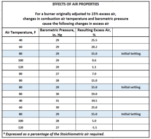
Notice the change in excess air levels as the temperature or barometric pressure changes. With a “decrease” in air temperature from original set point, and without any corrective adjustment, excess air climbs resulting in inefficient combustion and wasted fuel.
Conversely an “Increase” in air temperature can greatly reduce excess air and not only render the burner inefficient, but if left uncorrected, can build carbon on the fireside of your heat exchanger. This can lead to extreme loss of efficiency and possible damage to other components that overheated since proper heat transfer could not take place in the exchanger. The reverse occurs with barometric pressure changes, but with similar results.
Further, in traditional burners, linkage assemblies can have inherent slippage and wear, (hysteresis) causing poor repeatability to fuel-air characterized inputs.
One solution is to upgrade your burner with direct, “Servo” type actuators on fuel butterfly and air damper(s) and can also include a flue-gas recirculation damper on Low NOx burners. New controls and drive units will greatly improve repeatability, improve emissions, and stabilize inputs by reducing linkage hysteresis and achieve constant burner air-fuel ratios.
Keep in mind, the above-mentioned air property effects remain in-play after converting to direct drive controller. This can be addressed by implementing an oxygen trim system. Oxygen trim systems include an oxygen cell (Zirconium Oxide) which constantly samples the exiting flue gases to provide electronic feedback signal to control logic. The controller then sends a corrective signal to “trim” (very slight adjustment) a drive servo, either air or fuel, bringing combustion back in line with original set point for peak efficiency.
Note: Oxygen trim systems do require periodic testing of the oxygen cells to make certain they have not been fowled, deteriorated, or compromised rendering them ineffective. Cell replacement can be costly. Check with your supplier on recommended replacement intervals and costs to maintain an Oxygen Trim system prior to purchase to ensure your ROI is beneficial with fuel and maintenance savings. Also, your energy provider may offer incentives in the form of rebates to have certain fuel saving technologies installed.
If you want more information about periodic combustion testing, fuel savings, energy rebates, combustion setting or wish to obtain information on upgrading your current burner equipment, please contact our office’s Aftermarket Services department for assistance.
Settings, Adjustment & Testing
It is often said that combustion setting is both an “ART” and a science, applying both equally to obtain the best possible outcome when setting combustion on a complex burner. Combustion setting should ALWAYS be done by trained professionals with a full understanding of the variables associated with each individual burner, as well the mechanics, electronics, chemical reaction of fuels and air producing the exothermic reaction resulted by these settings.
Burner technicians use a stack gas analyzer while making burner adjustments for clean, efficient combustion. Adjustments normally take place when the boiler is up to normal operating pressure and temperature since a hot furnace will create different combustion results than a cold furnace. In addition, it is good practice to view flame pattern via sight glass at the back of the boiler to ensure there is no flame impingement and that refractory or insulating material integrity exists.
This is what that process might look like:
- Read and understand the manufactures recommended procedures, setting and operating instructions for the specific burner to be set.
- Make certain to have tools necessary for adjustments, including but not limited to, special wrenches, lubricants (if required), pressure and temperature gauges with ranges to match burner requirements, laptop, or other computing device as necessary, access to platforms/ladders if required to reach flue gas outlet port and a calibrated combustion analyzer for certified results.
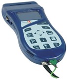 Hand-Held Combustion Analyzer
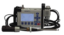
Advanced Combustion Analyzer
- Adjustment Variables: Understand variables associated with the process of combustion such as the fuel delivery system, gas or oil pressures available, economizer and assuring the venting is clear (more on venting and draft in Part 3).
-
- Adequate Combustion Air: To assure adequate combustion air is available, check louvres and combustion air interlocks for proper operation. If “sealed combustion” via direct duct from outdoor to boiler/burner is used, filters or mesh intake should be free of dirt, dust, lint, or debris such as bird nests & spider webs.
- Boiler Load: When preparing to perform combustion setting and/or testing, a boiler load should be available or another way to disperse generated heat, to avoid auto shut down if set points are quickly reached most likely during higher firing rates.
- Adjusting Combustion: When adjusting combustion at low fire with linkage or servo-driven equipment, test fire the burner multiple times after low fire adjustments to ensure excess air has not adversely affected the pilot light-off setting.
-
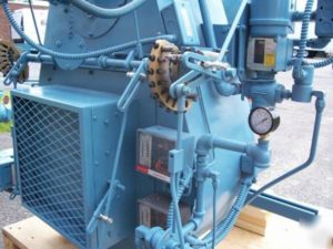
- Standard Linkage System
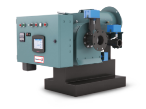
Servo-Drive Air-Fuel System
Gas Meter: During initial combustion setting at high fire on gas, make certain to clock the gas meter. Pressure and/or temperature correction factors must be applied to your input readings. Necessary changes must be made to compensate for accuracy before proceeding, then final readings should be recorded on report.
- Overfire or Low Fire: Most manufactures provide combustion air fans that will produce significant overfire air for safety reasons, however this can allow “overfiring” a boiler resulting in damage if not caught and corrected by accurate fuel meter input readings. Gas meter readings at low fire are also important so burner’s turn-down ratio design is not exceeded.
- Final Adjustment: Tighten and/or lock all linkages, set-screws, brackets etc. after final adjustment is made and record set points. Linkage can be marked and photos taken to illustrate how burner settings were finalized.
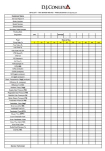
- Recording and Reporting: Record all settings on proper forms which include blocks for all readings in harmony with type of adjustments the owner requested. For example if simple “testing” with no adjustments, a basic combustion form can be used. If customer requires more stringent MACT type testing, then advanced forms must be used to outline procedures and include advanced details not normally required for owner’s submittal process.
Some newer burners operate on the “zero-governor” principle requiring minor or no seasonal adjustment to fuel valve setting since air will aspirate with fuel on a 1:1 basis. As air temperature & pressure changes, fuel increases or decreases accordingly.
During the process of combustion “testing-only” readings (O2, CO & Co2) outside acceptable manufacture parameters require investigation. Return burner to low fire position then shut down. Lock-out, tag-out burner’s electrical feed and notify the customer for adjusting approval. Do not re-employ a burner that is out of adjustment without proper correction and recording.
Sample of a combustion form:
For further information or if you have need for setting and testing combustion on your boiler, please contact your service provider for assistance.
Hope to see you next month for Part 3 of “Combustion”, covering boiler/burner flue stack & draft.
Information in this blog is furnished by D. J. Conley Associates Inc. and by those having numerous years of experience in design, installation, and application with generation of heating and process steam and hot water products and services. This information along with supplemental data obtained from a variety of sources is for the beneficial use of its audience only. We cannot be held liable for the application or misapplication of products or methods associated with this data which may cause unfavorable issues or harmful outcomes since there are many circumstances beyond our control at play in every individual system. You are welcome to contact us in the event questions should arise.


