All Posts By

Mike Conley

Wet and Dry Boiler Storage – August 2021

By | Retrofit Burners & Burner Controls

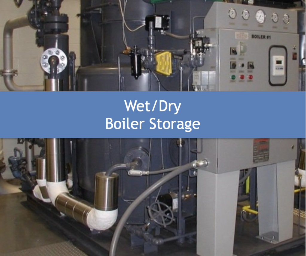
WET & DRY BOILER STORAGE METHODS:

In this blog we will examine proper procedure for short and long-term boiler storage. Certain boiler owners that don’t use their boilers for steam or hot water processing perform storage techniques each year, in effort to keep those boilers not required for process or comfort heat from corrosion. Though not inclusive, the storage process can greatly eliminate missteps that can lead to costly repairs after boilers are shut down for the season. 

Best Practice: There are two (2) basic methods of laying up a boiler for extended periods of time; wet and dry storage.

Short Term Storage: Though Wet or Dry is acceptable, wet storage may be beneficial due to lower overall water loss along with time & material (chemicals & absorption media) savings. 

Long Term Storage: Dry storage is the best method. This avoids the normally wetted steel surfaces from experiencing advanced corrosion. See details that follow.


Wet Storage

1) If the unit is to be stored for no longer than a month and emergency service is required, wet storage is satisfactory. Wet storage is not generally employed for boilers that may be subjected to freezing temperatures. Several alternative methods may be employed.

  • The boiler to be stored should be closed and filled to the top with chemically treated feedwater or condensate, to minimize corrosion during standby storage.
  • Water pressure greater than atmospheric pressure should be maintained within the boiler during the storage period.
  • A tank may be connected to the highest vent of the boiler to maintain statis head pressure above that of atmospheric pressure.
  • For short periods of wet storage, the water or condensate in the boiler should contain approximately 450 PPM of caustic soda and 200 PPM of sodium sulfite. Similar products may be used as recommended by your water chemist.
  • If the boiler is equipped with a superheater of the drainable type, it can also be filled with the above, described treated water by overflowing from the boiler vessel.
  • If the superheater is non-drainable, it should be filled with condensate or demineralized water containing no more than 1 PPM of dissolved solids. Before introducing the water into the superheater, sufficient hydrazine should be added to achieve a concentration of about 200 PPM.
  • Sufficient volatile alkali should also be added to produce a pH of 10. The treated water may be introduced into the superheater through an outlet header drain until the water flows into the boiler. When the superheater is filled, close the vents and drains. This quality of water may also be used in the boiler.
  • If the storage period should extend beyond a month, the concentration of hydrazine 1should be doubled.

2) As an alternative, the boiler may be stored with water at normal operating level in the drum and nitrogen maintained at greater than atmospheric pressure in all vapor spaces.

  • To prevent in-leakage of air, it is necessary to supply nitrogen at the vents before the boiler pressure falls to zero as the boiler is coming off the line.
  • If boiler pressure falls to zero, the boiler should be fired to re-establish pressure and drums and superheaters thoroughly vented to remove air before nitrogen is admitted.
  • All partly filled steam WET STORAGE drums and superheater headers should be connected in parallel to the nitrogen supply.
  • If nitrogen is supplied only to the steam drum, nitrogen pressure should be greater than the hydrostatic head of the longest vertical column of condensate that could be produced in the superheater, or a minimum of 5 psi. 3.
  • Rather than maintain the water in the boiler at normal operating level with a nitrogen cap, it is sometimes preferred to drain the boiler completely, applying nitrogen continuously during the draining operation and maintaining a pressure of nitrogen greater than atmospheric throughout the draining and subsequent storage.

Dry Storage

Dry storage is preferable for boilers out of service for extended periods of time or in locations where freezing temperatures may be expected during standby.

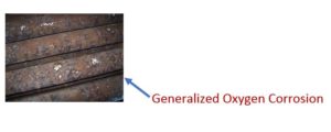
  • The cleaned boiler should be thoroughly dried, since any moisture left on the metal surface would cause corrosion.
  • After drying, precautions should be taken to preclude entry of moisture in any form from steam lines, feed lines, or air.
  • A moisture absorbing material should be used, such as quicklime, at the rate of two (2) pounds, silica gel or Drierite at the rate of five (5) pounds for 30 cubic feet of boiler volume. It may be placed on desiccant trays inside the drums or inside the shell to absorb moisture from the air.
  • The manholes should then be closed and all connections on the boiler should be tightly blanked.

The effectiveness of the materials for such purposes and the need for their renewal should be determined through regular internal boiler inspections.

We would strongly recommend that large signs be placed in conspicuous places around the boiler to indicate the presence of moisture absorbing materials. The message to be conveyed can be as follows: Note: Moisture absorbing material has been placed in both the fireside and waterside of this boiler. These materials must be removed before any water is introduced into the boiler and before the boiler is fired.

For long periods of storage, internal inspections should be performed to assess the condition of the moisture absorbing materials. Such inspections should be initiated monthly, unless experience dictates otherwise. The moisture absorbing material increases in volume as moisture is absorbed, making it necessary to use deep pans. Fresh material should be substituted as needed at the time of the inspection. Alternatively, air dried externally to the boiler may be circulated through it. The distribution should be carefully checked to be sure the air flows over all areas.


Other Protections:

Boilers stored in other than a dry, warm protected atmosphere, should have exterior component protection. Also, common vented boiler consideration included below.

  • Burner components that are subject to rust, such as jackshaft, linkage, valve stems, moving parts, etc., should be lightly coated with a rust inhibitor and covered to protect them from moisture and condensation.
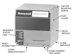
  • Electrical equipment, electronic controls, relays, switches, etc., should be similarly protected.
  • Pneumatic controls, regulators, diaphragm or piston operated equipment should be drained or unloaded and protected so that moisture, condensation, rust, etc. will not damage the equipment during a long period of storage.
  • Feedwater lines, as well as blowdown, soot-blower (if equipped), drain lines, etc., should all be drained and dried out.
  • Valve stems, solenoid valves and diaphragms should all be protected by lubricant, rust inhibitors, plastic coverings or sealants.
  • Where boilers are “common vented” and only one boiler will be stored, be sure to seal or block-off & VISUALLY TAG vent opening at the flue gas outlet to eliminate possible moisture and potential flue gas entry from the fireside via down or backdraft. Monoxide detection alarm in boiler room recommended.


Consult your boiler water treatment professional if further guidance is required.
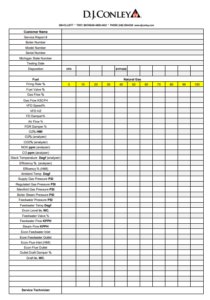
Customer Service:

Our Service Team is ready to assist in preparing to store your boiler or bringing your boiler out of storage in preparation for the upcoming heating season. This includes, cleaning, replacing filters, re-gasketing, filling, closing and firing your boiler(s).  Additionally, we can perform your CSD-1 testing and reporting along with combustion checks and/or setting and offer recommendations which can help you save on annual fuel costs. Visual inspection and function testing of critical components to reduce emergency and demand maintenance costs are also done at this time.

Contact one of our team professionals to obtain pricing or schedule your service visit.

CALL (248) 589-8220Service: Brian Frank at EXT. 116   or   Lou Willoughby at EXT. 123

                                    Scheduling: Debra Smalstig at EXT. 117  or  Brian Frank at EXT. 116


Storage basics Courtesy of Cleaver-Brooks w/supplemental commentary by:

M. Conley / D. J. Conley Associates Inc. 1974 – present.


Retrofit Burners & Burner Controls – July 2021

By | Retrofit Burners & Burner Controls

In this blog we cover general steps when faced with the decision to replace older outdated burners vs. a complete boiler replacement.

Whether your consideration to replace comes from a poorly functioning burner, the drive to become more environmentally friendly, improve performance & reliability, increase efficiency or a combination of factors, the following will provide guidance to help achieve your goals.

1. Verify your boiler’s condition and expected longevity.

    • Perform internal fireside and waterside inspection to ensure vessel integrity and insulating materials are in good condition and repair/ replace components, as necessary.
    • Consider boiler life expectancy and costs associated with reaching boiler end date with respect to other ancillaries that may need replacement.
    • Upon review of results, determine if proceeding to step 2 is viable.

2. Employ a reputable burner supplier & installer to establish the budget.

    • Determine if your burner project will require an “air permit” through Michigan DEQ/EGLE, (Department of Environment, Great Lakes & Energy), AQD (Air Quality Division).
    • Select burner type to match goals. Fuel type, standard or low NOx, Single-Point- Linkage vs. Parallel Position, Linkage-less, Burner firing rate control. (See illustrations below)
    • Select emission level required or expected. Generally, in SE Lower Michigan under Boiler MACT, below 10 MMBTU/Hr. burning natural gas will expect new burners to be 30 PPM NOx or less emission level.
    • Determine if emission level be achieved will be via FGR (flue gas recirculation) or by internal burner design w/o FGR. Installed cost & blower horsepower (operating costs) normally affect this decision.
    • Establish burner turndown required. Most conventional replacement burners today depending upon capacity and fuel burned, will deliver anywhere from 5 to 10:1 turndown. Verify offering with customer expectation with all associated fuel(s) to be used.
    • Consider VFD (variable frequency drive) as part of control strategy for better combustion control and electrical energy savings. Weigh added cost vs. potential payback. VFD does not make sense for all size & type projects. Payback using VFD on small burner/boiler used for comfort heat only may not make sense.
    • Combustion and Firing rate controls: Consider overall control strategy to compliment chosen burner using technology that best fits your plant’s operation and budget. Discuss & decide flame safeguard & scanner type, load demand and duty cycle with firing rate control from main or “master” panel (multiple boilers/burners), diagnostics, connectivity to remote device, phone app or BMS, alarm options, implementation of oxygen trim system, reporting and recording options via SCADA, PC, HMI screen size (if required) & boiler level control upgrades.

*   See “prométha connected solutions below for example.

    • Confirm boiler/burner “altitude” at installed location. Elevations above 2000 ft. ASL warrant review by an application engineer to confirm fan size or necessity to de-rate burner output affecting rated performance.
    • Consider new burner’s sound pressure levels (dbA at “X” Hz) at all firing rates to verify acceptability.
    • Provide engineering documentation to confirm burner fit and operation with existing boiler’s flange mount, combustion chamber and gas passage area, through stack, breeching, economizer, or other pressure drops to outlet. No excessive back pressure or adverse combustion conditions should arise with normal burner operation at rated capacities. Larger and Industrial boiler/burners with stringent NOx requirements and/or larger furnace areas may require computational fluid dynamic (CFD) analysis to best match new burner with boiler.
    • Burner supplier should provide an “engineered” stack loss calculation for proper verification of expected and acceptable draft conditions.

 3. Review budgetary or firm proposed price.

    • Determine if ROI fits within boiler’s expected life.
    • Consider potential for unforeseen repairs or modifications.
    • Secure funding.   

4. Proceed with investigation of required details.

    • Confirm fuel(s) to be used.
    • Verify fuel delivery system’s integrity including piping, fuel regulation, isolation valves, vents, strainers etc., are operable and up to current code requirements. Repair/replace, as necessary.
    • Confirm gas pressure required at the inlet to the burner and at inlet to fuel train is available and deliverable to fuel train inlet with existing transmission piping.
    • Required electrical service is available and costs include any service upgrades needed to implement new burner electrical feed, low and high voltage along with any required BMS interface, connecting testing and upgrades to existing systems.
    • Consider if UPS/Surge suppressor will be expected or required. Strongly suggest using UPS/Surge suppressor if using PLC type controls.
    • If using IP protocols, verify via coordinated effort with installer, controls contractor and owner for clean integration between new and existing control connections.
    • If using a stand-alone internet connection for remote boiler/burner monitoring, such as prométha shown below; confirm all hardware such as modems, power supply, software, mounting, wiring and set-up are included.
    • Confirm installer has included costs for mechanical/electrical and other permits as required.
    • Obtain formal quotation with firm or “not-to-exceed” pricing and agree on T’s & C’s along with labor & material warranty terms.
    • Verify lead times and project completion expectations.
    • Receive copy of all documentation, including but not limited to, permit application(s), Insurance, and installer’s License.

5. Once formal purchase order has been given and prior to release for production:

    • Receive and review submittal information with project team confirming fit, layout, coordination, and sequence of installation.
    • Confirm fuel train layout & inlet location is acceptable and make final changes if needed.
    • Determine drop-ship location, equipment receipt process and materials protection prior to installation.
    • Review all owner safety requirements and provisions, house-keeping measures and site logistics with team and perform sign-off process.

6. Project Completion:

    • Review entire installation for proper completion, including wiring continuity checks, burner and controls mounting, fuel delivery system leak testing and all other (FGR) piping, gaskets, and seals as necessary.
    • Test, check & start new burner, combustion and firing rate controls and other new products as part of project.
    • Submit written documentation of all test procedures, combustion reports and CSD-1 test reports as required.,
    • Call local jurisdiction for inspection. Note: certain jurisdictions may require inspection prior to startup. Verify first.
    • Perform “witness testing” with owner and obtain sign off.
    • Perform operator training, review O & M manuals and review maintenance procedures with owner/operator.
    • Review spare parts (if needed) and purchase points.
    • Sign off project completion documentation “as-built” drawings and close out project.Note: The above will vary with project, however, should provide a general process for your BURNER REPLACEMENT consideration.


See Illustrations to assist in understanding basic options:
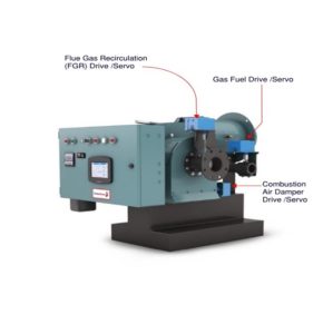
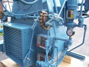
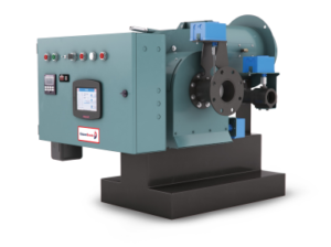
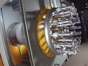
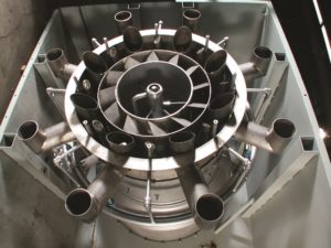
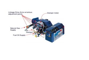
A Typical Standard burner single point positioning / jackshaft control

Typical Burner with Parallel Position Controls

LOW NOx Burner / NO FGR Required with Parallel Position Controls


protha” Connected Boiler Solutions:

    • Load Management
    • Boiler/Burner Diagnostics
    • Deaerator–Surge Tank Feedwater System Management


A variety of reliable connected solutions are available for your consideration.

Please contact our sales team below.

 D.J. Conley has supplied quality Cleaver-Brooks ProFire®/ Industrial Combustion retro-fit burners to the SE Michigan boiler market for nearly 50 years. Our commitment to quality assures your satisfaction. We regularly partner with our contracting community to provide turn-key installations. Give us a call to assist in your next burner project or for a free evaluation of your current boiler/burner system!

Contact us at (248) 589-8220 and ask for Aftermarket Sales or email:  aftermarket@djconley.com

For more information, go to  www.djconley.com   click on “Products”, then scroll to “Boiler Burners”.

Author: M. Conley / D. J. Conley Associates Inc. 1974 – present.

Information in this blog is being furnished by D. J. Conley Associates Inc. and by those having numerous years of experience in design, installation, and application with generation of heating and process steam and hot water products and services. This information along with supplemental data obtained from a variety of sources is for the beneficial use of its audience only. We cannot be held liable for the application or misapplication of products or methods associated with this data which may cause unfavorable issues or harmful outcomes since there are many circumstances beyond our control at play in every individual system. You are welcome to contact us in the event questions should arise.

Combustion – Part 3

By | Combustion | No Comments

Part 3 of 3 – Flue Gas Stack & Draft

In our final blog series on combustion, we will cover a vital component to proper boiler/burner operation, Stack Draft!

Flue gas draft or “stack effect” is established by the pressure and temperature difference between inside and outside the stack and building. As hotter, less dense gases inside the bottom of the stack rise, draws in cooler, higher (combustion)air pressure. The higher external air pressure moves combustion air into a natural draft burner for the combustion process. Other factors that affect draft are wind fluctuations, chimney height, burner firing rate, air heaters, stack economizers, dampers or other fittings and barometric conditions. The varying conditions are in a constant state of change. To counter these changes, engineers design flue gas systems that take flue stack & breeching size design, layout, burner/boiler type and ancillary equipment into consideration. Varying draft conditions can affect combustion therefore must be understood to provide stable, trouble free combustion within the envelope of mechanical code. Too little or too much draft can create a variety of problems such as poor burner light off, combustion rumbles, varied fuel inputs, pilot failures, stand-by heat losses and could even void equipment warranties if not addressed and corrected.

Chimney Stack Effect: See example below.

The absolute air pressure (Pa) to (P1) at boiler/burner entrance and (P2) at boiler/burner exhaust outlet and entrance to stack shows the airflow as the hotter more buoyant air rises indicated with arrows.

Following Describes draft type and how they are controlled:

  • Natural draft: Natural draft in a flue gas stack system is created as described in detail above. Natural Draft Systems can also be controlled by inlet/outlet dampers. Natural draft effect exists in atmospheric, fan assisted and forced draft systems as well.
  • Forced draft: Air and flue gases are maintained by a motor driven fan to produce pressures above atmospheric. The forced draft fan system is normally a jet type or integrated into the boiler/burner design, forcing primary combustion air through a plenum, directing air flow through a diffuser or similar, to mix with fuel flow at set levels creating stable combustion.
  • Induced draft: Air or flue gases flow under the effect of a gradually decreasing pressure below atmospheric pressure. In this case, the system is said to operate under induced draft, the stack or chimney can provide sufficient natural draft to meet the low draft losses. To achieve higher pressure differentials, the stacks must simultaneously operate with draft fans and controls to maintain proper draft setting.
  • Balanced draft: When the static pressure is equal to the atmospheric pressure, the system is referred to as balanced draft. Draft is said to be zero in the system, however, must rely upon accurate controlled FD (Forced Draft) fan and often, ID (Induced Draft) fan and/or damper operation to ensure constant flue gas exit to atmosphere.

Note: Mechanical Draft systems shall be listed in accordance with UL 378, “Draft Equipment” and installed in accordance with both the appliance and the mechanical draft system manufacture’s installation instructions.

With any stack system design, draft must be kept within the manufacturers draft tolerance for safe, trouble free operation.

Design considerations must also factor ancillary products into the equation as previously mentioned such as air heaters, stack economizers, damper, or other fittings along with losses from internal stack surface.

Materials of construction must be considered to match the appliance category for compliance with code and to mitigate premature failure of stack & breeching selected. More on venting categories below.

Very tall individual or combined venting stack systems may require utilizing sequence draft control due to draft variance created in the system from multiple burners and their associated turn-down. Stack heights are dictated by building and mechanical code and/or State mandates during the air permitting process. A draft calculation should accompany all combined venting designs and those beyond a simple short vertical stack or that which is defined in the manufacture’s installation manual.

On large power plants, the required stack height design may include CEM (Continuous Emission Monitoring) systems and/or annual MACT testing to obtain or maintain an operating permit. These mandates can become very costly therefore it is best to understand the potential requirement up front for feasibility and budgeting.

Though this blog centers on combustion, draft being a major component for proper combustion, this is a good place to offer some additional information on draft venting material and use within a boiler system. The following 4 venting categories will provide some insight as to previously mentioned materials of construction for prefabricated and welded or site-built stack systems.  

Category I: Natural Draft (non-pressurized) venting systems serving one or more listed appliances equipped with draft hood or listed for use with Type B gas vent usually residential or commercial appliances installed in the single story of a building and is of the non-condensing type of unit. This can also include “fan-assisted” gas appliances that operate with neutral or negative draft. Stack materials are often single or double wall and made from galvanized or aluminized steel.

Category II:  Category II venting is for a “condensing” appliance that operates with a non-positive (neutral or negative) vent. Stack materials are usually single or double wall with the inner wall made from special stainless steel to avoid corrosion from condensation.

Category III: A non-condensing gas appliance that operates with a positive vent pressure. These are equipped with a forced draft robust burner-blower motor and can normally overcome slight stack system back pressure manufactures instructions. Materials are usually double wall aluminized or stainless steel based on fuel being burned, budget and customer preference.

Category IV:  A condensing gas appliance that operates with a positive vent pressure as listed. Stack materials are usually double wall with inner wall being a special stainless steel to avoid corrosion from condensation.

For more information on stack categories, See illustration below and NFPA 54, ANSI Z223.1 or the International Fuel Gas code (IFGC 2021)

When designing a gas venting system with an “in-line” induced draft fan, keep in mind all stack materials “downstream” of the induced draft fan must comply with Category III or Category IV material accordingly. Also, it must be understood, that though many manufactures allow and list their appliance for use with (code approved) PVC & CPVC venting material, those materials have the inherent danger of being compromised if mechanical, electrical systems or high limit temperature sensor failure occurs. Upon failure, plastic pipe can split or melt resulting in the release of carbon monoxide to occupied areas. Though this may seldom happen, one must question if material & installation cost difference is worth the risk. We recommend using all non-combustible metals, stainless steel and/or stainless lined refractory stacks to avoid this potential.

Draft & Barometric Dampers:  Barometric dampers on stack and breeching systems are often used to address excessive draft conditions in category 1 venting by using a counter-balance blade-type damper, normally installed at the base of the stack or far end of the breeching.

These types of damper arrangements are limited by code, however, many stack and breeching systems that were originally designed into Category III and IV appliance systems were either grandfathered due to age, or permission granted by local jurisdiction where other systems would simply not work. Before implementing a barometric damper into a stack system, make certain to obtain approval from the boiler manufacture, engineer and local inspector having jurisdiction over the installation. Some installations may require a carbon monoxide detection and alarm system to ensure safe shut-down w/alarm in case of damper spillage.

In summary: boiler/burner combustion can be complicated. It is best to understand design intent, application, installation, code requirements and equipment specifications prior to setting or trouble shooting combustion. Linkage, servos, manual and automatic gas valves, regulators, gaskets, seals, insulating materials, refractory, diffusers, gas housings and ports all play an important role in solid repeatable combustion along with a well-designed venting system and can provide 30 plus years of reliable service to an owner. Final thought regarding burner tune-ups and maintaining proper combustion; if your burner’s air-fuel ratio is too lean, un-stable combustion & efficiency loss from high excess air levels can be expected; if too rich, not only can you “overheat” boiler metals, heads, flanges, gaskets, and insulating materials to the point of costly repairs, risk the loss of efficiency and face expensive clean-up from soot deposits on the fireside and stack system.

See chart below for an example of potential energy loss due to soot build-up in a boiler.

Other resources: Guide for Boiler Tune-Up can be found here:

https://www.epa.gov/sites/production/files/2016-09/documents/tune-up_guide.pdf

We hope you found this quick journey through Boiler-Burner combustion & draft informative and useful.

Please drop us a line if you wish to learn more. Our expert Sales & Service Specialists are here to assist you in the design, application and troubleshooting of new and existing boiler/burners, Low NOx burners & controls, engine exhaust, commercial/industrial laundry, coffee roasters and pizza ovens.   

We hope to see you back in our next blog when we take a closer look at burners and burner Control Systems.

Information in this blog is being furnished by D. J. Conley Associates Inc. and by those having numerous years of experience in design, installation, and application with generation of heating and process steam and hot water products and services. This information along with supplemental data obtained from a variety of sources is for the beneficial use of its audience only. We cannot be held liable for the application or misapplication of products or methods associated with this data which may cause unfavorable issues or harmful outcomes since there are many circumstances beyond our control at play in every individual system. You are welcome to contact us in the event questions should arise.

Combustion – Part 2

By | Combustion

PART 2 of 3 –  Fuels, Setting, Adjustment & Testing

FUELS

The combustion process of converting fuel to energy, not as popular as the international push toward carbon neutrality and emission reduction, still remain a vital force in producing steam and hot water via conventional and hybrid burners. Common fuels such as natural gas & propane come standard on most new boiler/burner systems. Alternate fuels such as bio-fuels, land-fill gas, methane from waste treatment facilities and ethanol from corn can be burned as primary, secondary or simultaneous fired configurations in some conventional boilers. Bio-mass fuels such as wood pellets, briquettes or logs and other raw materials are also used to fuel boilers.  Gas fired boiler/burners, light fuel oils such as kerosene, #2 fuel oil and in some cases heavier oils which must be heated prior to use are often used as a reliable back-up fuel source. The above alternative liquid fuels come with more stringent regulation.  They are most notably selected as back-up fuel at critical care facilities such as hospitals or in remote areas where other gaseous or alternate fuels and not readily available or too costly deliver. Alternative fuels, solid (bio-mass) or liquid used today require a special permitting process. Though all states are governed by the U.S. EPA Federal Register’s latest version of 40 CFR. each state may have additional regulations as well. The idea is that replacement commercial & Industrial boilers with fuel burners, along with other larger fuel burning equipment such as kilns, incinerators and other industrial burn processes, are less polluting than previous versions.

In Michigan, these and other added sources require prior approval from the Michigan DEQ/EGLE, (Department of Environment, Great Lakes & Energy), AQD (Air Quality Division) who have been given authority by U.S. EPA to govern the permitting process.

You can navigate this complex process regarding NESHAP (National Emission Standard for Hazardous Air Pollutants) otherwise known as Boiler MACT (maximum achievable controls technology), by following this link:

https://www.michigan.gov/egle/0,9429,7-135-3310-262365–,00.html

Application must be submitted prior to procurement and follow the NSPS (new source performance standards).  To learn more from the U.S EPA, follow this link:

 https://www.energy.gov/eere/amo/boiler-mact

There exists a plethora of rabbit trails to continue down with regards to emissions, though not the intent of this blog.  

If you should have a need to explore the use of any of these fuel options mentioned, please contact our sales professionals who can assist you in system design and selection of the right burner/boiler combination for your facility.  

The Importance of Settings, Adjustments & Testing

Air properties change with air temperature and barometric pressure which directly effects the combustion process. 

To operate your boiler’s burner at optimal efficiency, settings should be made to coincide with these atmospheric changes. On larger commercial and Industrial boilers, minor corrections to combustion settings to maintain constant fuel-air ratios can result in fuel savings to the owner. See “Effects of Air Properties” chart below. Typical excess air levels are set at 15% during the start of a new boiler or at the beginning of a heating season. 

Notice the change in excess air levels as the temperature or barometric pressure changes. With a “decrease” in air temperature from original set point, and without any corrective adjustment, excess air climbs resulting in inefficient combustion and wasted fuel.

Conversely an “Increase” in air temperature can greatly reduce excess air and not only render the burner inefficient, but if left uncorrected, can build carbon on the fireside of your heat exchanger.  This can lead to extreme loss of efficiency and possible damage to other components that overheated since proper heat transfer could not take place in the exchanger. The reverse occurs with barometric pressure changes, but with similar results.  

Further, in traditional burners, linkage assemblies can have inherent slippage and wear, (hysteresis) causing poor repeatability to fuel-air characterized inputs.

One solution is to upgrade your burner with direct, “Servo” type actuators on fuel butterfly and air damper(s) and can also include a flue-gas recirculation damper on Low NOx burners. New controls and drive units will greatly improve repeatability, improve emissions, and stabilize inputs by reducing linkage hysteresis and achieve constant burner air-fuel ratios.

Keep in mind, the above-mentioned air property effects remain in-play after converting to direct drive controller. This can be addressed by implementing an oxygen trim system. Oxygen trim systems include an oxygen cell (Zirconium Oxide) which constantly samples the exiting flue gases to provide electronic feedback signal to control logic.  The controller then sends a corrective signal to “trim” (very slight adjustment) a drive servo, either air or fuel, bringing combustion back in line with original set point for peak efficiency.

Note: Oxygen trim systems do require periodic testing of the oxygen cells to make certain they have not been fowled, deteriorated, or compromised rendering them ineffective.  Cell replacement can be costly. Check with your supplier on recommended replacement intervals and costs to maintain an Oxygen Trim system prior to purchase to ensure your ROI is beneficial with fuel and maintenance savings. Also, your energy provider may offer incentives in the form of rebates to have certain fuel saving technologies installed.   

If you want more information about periodic combustion testing, fuel savings, energy rebates, combustion setting or wish to obtain information on upgrading your current burner equipment, please contact our office’s Aftermarket Services department for assistance.

Settings, Adjustment & Testing

It is often said that combustion setting is both an “ART” and a science, applying both equally to obtain the best possible outcome when setting combustion on a complex burner. Combustion setting should ALWAYS be done by trained professionals with a full understanding of the variables associated with each individual burner, as well the mechanics, electronics, chemical reaction of fuels and air producing the exothermic reaction resulted by these settings.

Burner technicians use a stack gas analyzer while making burner adjustments for clean, efficient combustion. Adjustments normally take place when the boiler is up to normal operating pressure and temperature since a hot furnace will create different combustion results than a cold furnace. In addition, it is good practice to view flame pattern via sight glass at the back of the boiler to ensure there is no flame impingement and that refractory or insulating material integrity exists.

This is what that process might look like:

  • Read and understand the manufactures recommended procedures, setting and operating instructions for the specific burner to be set. 
  • Make certain to have tools necessary for adjustments, including but not limited to, special wrenches, lubricants (if required), pressure and temperature gauges with ranges to match burner requirements, laptop, or other computing device as necessary, access to platforms/ladders if required to reach flue gas outlet port and a calibrated combustion analyzer for certified results.

Hand-Held Combustion Analyzer


Advanced Combustion Analyzer

  • Adjustment Variables: Understand variables associated with the process of combustion such as the fuel delivery system, gas or oil pressures available, economizer and assuring the venting is clear (more on venting and draft in Part 3). 
    • Adequate Combustion Air: To assure adequate combustion air is available, check louvres and combustion air interlocks for proper operation. If “sealed combustion” via direct duct from outdoor to boiler/burner is used, filters or mesh intake should be free of dirt, dust, lint, or debris such as bird nests & spider webs.  
    • Boiler Load: When preparing to perform combustion setting and/or testing, a boiler load should be available or another way to disperse generated heat, to avoid auto shut down if set points are quickly reached most likely during higher firing rates.
    • Adjusting Combustion: When adjusting combustion at low fire with linkage or servo-driven equipment, test fire the burner multiple times after low fire adjustments to ensure excess air has not adversely affected the pilot light-off setting.
  •  
  • Standard Linkage System

Servo-Drive Air-Fuel System

Gas Meter: During initial combustion setting at high fire on gas, make certain to clock the gas meter. Pressure and/or temperature correction factors must be applied to your input readings. Necessary changes must be made to compensate for accuracy before proceeding, then final readings should be recorded on report.

  • Overfire or Low Fire: Most manufactures provide combustion air fans that will produce significant overfire air for safety reasons, however this can allow “overfiring” a boiler resulting in damage if not caught and corrected by accurate fuel meter input readings. Gas meter readings at low fire are also important so burner’s turn-down ratio design is not exceeded.
  • Final Adjustment: Tighten and/or lock all linkages, set-screws, brackets etc. after final adjustment is made and record set points. Linkage can be marked and photos taken to illustrate how burner settings were finalized.
  • Recording and Reporting: Record all settings on proper forms which include blocks for all readings in harmony with type of adjustments the owner requested. For example if simple “testing” with no adjustments, a basic combustion form can be used. If customer requires more stringent MACT type testing, then advanced forms must be used to outline procedures and include advanced details not normally required for owner’s submittal process.

Some newer burners operate on the “zero-governor” principle requiring minor or no seasonal adjustment to fuel valve setting since air will aspirate with fuel on a 1:1 basis. As air temperature & pressure changes, fuel increases or decreases accordingly.

During the process of combustion “testing-only” readings (O2, CO & Co2) outside acceptable manufacture parameters require investigation. Return burner to low fire position then shut down. Lock-out, tag-out burner’s electrical feed and notify the customer for adjusting approval. Do not re-employ a burner that is out of adjustment without proper correction and recording.

Sample of a combustion form:

For further information or if you have need for setting and testing combustion on your boiler, please contact your service provider for assistance.

Hope to see you next month for Part 3 of “Combustion”, covering boiler/burner flue stack & draft.

Information in this blog is furnished by D. J. Conley Associates Inc. and by those having numerous years of experience in design, installation, and application with generation of heating and process steam and hot water products and services. This information along with supplemental data obtained from a variety of sources is for the beneficial use of its audience only. We cannot be held liable for the application or misapplication of products or methods associated with this data which may cause unfavorable issues or harmful outcomes since there are many circumstances beyond our control at play in every individual system. You are welcome to contact us in the event questions should arise.


Combustion – Part 1

By | Combustion

PART 1 OF 3

Greetings and Welcome back to our blog series!

In keeping with world events this past year, we would like to present our version of volatility better known as the process of combustion in conventional boilers. The goal is to take you on a short journey through the basic concept of combustion including its process, application, effects, fuels, along with sequence of operation, checking (testing) & setting combustion as related to commercial & industrial boilers. So let’s fire it up!

We will first review basic process as we begin to better understand safe-reliable burner combustion in a boiler. Chances are you benefit from the combustion process in your daily life, driving an automobile, cooking, heating your home or a variety of other ways. You were likely exposed at an early age to the direct process of combustion watching your folks build a campfire or playing with blue-tip stick matches to ignite your favorite tobacco, experimenting with alcohol lamps or Bunsen burners in a school lab. Combustion is all around us.

There are three basic components that must be present in combustion for this chemical reaction to take place.

  1. Oxygen
  2. Fuel
  3. Heat (spark or other means)

Better illustrated by the common triangle shown below.

To obtain safe, reliable burner combustion, the above 3 elements must be introduced at the right time and quantity.

For sustained effective and efficient combustion, we follow the Three T’s of time, temperature, and turbulence.

The Time of combustion refers to rate of reaction. Fuel (natural gas, propane etc…), is introduced to the combustion zone as described in the steps below. The volumetric rate is metered by burner architecture via orifices, lances, spuds or other similar means. Size and quantity of these delivery methods result in gas velocity and volume required to achieve rated capacities and limit emissions during the resident time in the main furnace.  Air-fuel ratios must be controlled to maintain stable, clean flame geometry within the furnace throughout various firing rates.

The Temperature of combustion is inherent to above attributes. Once we establish the primary or main flame (see sequence below), the heat present will maintain the temperature to continue the chemical reaction.

The Turbulence of combustion comes from the introduction method of fuel with air mixing and is vital to achieving stable and complete combustion. As a result, methods used will help to abate VOCs (volatile organic compounds) including  reducing carbon monoxide and nitrogen oxide (NOx) emission. Boiler furnace and refractory design play an important role in turbulence produced to effect an efficient clean flame pattern.

CFD (Computational Fluid Dynamics) modeling is complex process often used to develop a good match between burner & boiler in commercial & Industrial boilers. This complex process will only be mentioned here due to the extensive analysis required for its development.

Example of an Industrial Low NOx burner (NatCom)


These combustion systems are designed and engineered on our burner-control systems, to meet the most stringent emission requirements mandated to date.

The Following steps outline the burner combustion flame sequence:

Step #1. A call for heat is signaled to the boiler’s flame safeguard (sequence) control. This control starts a combustion air fan (oxygen) which in-turn energizes a pressure switch confirming fan air pressure. The boiler’s burner fan is engineered by the manufacture to produce enough combustion air to fire the burner at its variable, min./max. capacity. The sequence controller initiates an internal timer to “pre-purge” combustion chamber to accomplish a minimum of four (4) complete air changes per code, through combustion chamber and flue passages to flue stack outlet prior to start. This code requirement offers inherent safety by removing residual unburned fuel or in the case of a leaking fuel valve, miniscule amount of fuel in the combustion chamber at light-off so as not to cause an explosive environment resulting in unwanted occurrence.

Step #2.  Once timed sequence of pre-purge is complete and all safety parameters met, air dampers are electrically positioned to start.

Note: Some burners often found on condensing boilers include VSD (variable speed drive) fan motors, increasing fan RPM for pre-purge, then decreases to a proper set point for light off to accommodate pilot fuel for light-off.

Step #3. Simultaneously a gas pilot solenoid valve opens, while an ignition transformer energizes spark or glow plug (heat) to ignite pilot (fuel) establishing pilot flame prior to main fuel valve opening.

Step #4. Pilot flame is confirmed via flame rectification (Scanner Cell or Flame Rod) to flame safeguard control where sequence is automatically advanced to allow for main fuel valve(s) to open establishing a low fire in the boiler’s combustion chamber.

Step #5. Once main fuel valve(s) is open and flame signal remains strong, pilot fuel valve and spark or glow plug are de-energized, the flame safeguard control releases burner operation for firing rate /modulation to the respective controller packaged with boiler or from remote signal from a Plant Master or other firing rate type control. Assuming boiler has been properly warmed, modulation control will position firing rate to match boiler load.

Step #6. When steam or hot water load is satisfied and system demand is less than fuel (energy) input by the burner in low fire – minimum firing rate, burner’s flame safeguard control will begin burner shut-down sequence. This process includes a “post-purge” time to eliminate unburned fuel from chamber and flue passages, prior to shut down. At this point the boiler/burner is ready to start the sequence over again upon demand.

Note: The sequence above is very general. There is a lot more going on electronically relative to the combustion process than what is mentioned in this blog.

For more information relative to the variety of products offered as new or retrofit in your existing boiler plant, contact our Sales or Parts department.

Typical Flame Safeguard Sequence Control

Hope to see you next month for Part 2 of “Combustion”, where we will look at boiler stack draft and different fuels as it relates to combustion.

 Information in this blog is being furnished by D. J. Conley Associates Inc. and by those having numerous years of experience in design, installation and application with generation of heating and process steam and hot water products and services. This information, along with supplemental data obtained from a variety of sources, is for the beneficial use of its audience only. We cannot be held liable for the application or misapplication of products or methods associated with this data which may cause unfavorable issues or harmful outcomes. There are many circumstances beyond our control at play in individual systems. You are welcome to contact us in the event questions should arise.

Boiler Waterside Care & Treatment – Part 3

By | Water Treatment | No Comments

In this final installment of Boiler Water Treatment, we will focus on the following three components:

  • Chemical Treatment Application
  • System Design/Treatment Injection Sites & Cautions
  • Signs Your Treatment Program Requires Attention

CHEMICAL TREATMENT APPLICATION

Evaluation and analysis of all facets of chemical treatment must be examined prior to implementation. 

Chemical treatment formulas have changed over the years along with applicability, codes, laws, and rules for safe use and compliance. A variety of material types and manufacturers are available; though many formulations are similar, application and follow up is key to a successful treatment program.

Due to other complexities like injection line type and size, distance to equipment being treated, and method / location of injection and pump types, proper evaluation is required to be sure the best solution is applied. Additional factors such as bulk delivery, storage, safe handling and use of PPE, along with liability and cost, help to determine the right fit for your treatment plan.

By partnering with your boiler supplier, engineer, and certified water professional, you can be confident the best treatment advice is provided.  Misapplication can lead to major loss, severe penalties, ruptures, spills, and poor treatment, including the potential for pollution, energy efficiency loss from mud / scale build-up, and equipment failure. Additionally, health concerns may exist from steam injection in humidification, sterilization, and food processing where toxic steam may come into contact with humans.

Example of boiler operating characteristics that demand different treatment methods.

A steam boiler operating at 10 psig with 10% soft water make-up, 3% blowdown, while receiving 87% condensed steam back in the form of hot treated condensate to the feedwater tank or deaerator with minimal “direct” steam use.
 

VS

A steam boiler operating at 100 psig, having 55% direct steam use such as sterilizers, humidification or other live steam injection, 5% blowdown (60% soft water make-up) and 40% return condensate.


Treatment Timeline

After your boiler has been installed and is ready for start-up, the process begins.

  • Steam Boilers: Boil-out should be employed per manufacturer recommendations.
  • Hot Water Boilers: If cleaning & flushing a new boiler with the entire hydronic system is the plan; be aware during the system flush, sediment may drop out in the boiler due to having the lowest delta P of all system components. This sediment can collect on tubes (Firetube) or in tubes (Watertube) and lower drum(s).
  • Proper boiler isolation, drain, and rinse is recommended after a combined boiler & system flush to ensure sediment, welding slag from manufacturing, and other particles are removed
  • Formal treatment injection should begin immediately upon boiler water fill.

A word about Boiler ECONOMIZERS on steam boilers: If you have multiple boilers, each having a flue gas economizer, and one or more boiler is in hot stand-by,  it is recommended that a by-pass line with orifice be installed. This will recirculate water from a common feedwater header at economizer, to outlet piping of economizers, back into the deaerator, allowing treated water to continually flow at a low rate through economizer to protect tubes from corrosion.

SYSTEM DESIGN / (POSSIBLE) TREATMENT INJECTION SITES

The system design below shows what a typical boiler plant can look like. Common treatment injection sites are shown by an ORANGE ARROW and will vary with each application.

SIGNS YOUR TREATMENT PROGRAM REQUIRES ATTENTION

There are specific markers given that are a red flag that your water treatment care program is in need of review and your boiler or related equipment requires attention or internal inspection. Here are a few of those markers:

  1. Water leaking around the base of your boiler (Watertube) or from under the front or rear head (Firetube Boiler) of your boilers.
    1. If, upon further inspection it is determined the water on the floor is not from typical condensation during warm up or other assembly deficiency and the boiler is up to temperature/pressure, we recommend the boiler is cooled and opened for internal visual inspection and possible hydrostatic testing.
    2. If signs of leakage appear to be coming from another source such as the boiler flue gas stack or economizer, further investigation into those areas is warranted.
    3. If boiler headers, shell and/or tubes appear to be the source, a hydrostatic pressure test is required to pinpoint cause.
  2. If boiler stack vapor (plume) is excessive in a non-condensing boiler, the same inspection as above is in order.
  3. If your boiler’s stack temperatures are excessive, replace temperature gauge with a calibrated gauge to ensure it is not defective.
    1. Once you determine gauges are accurate, inspect the waterside for scale and/or mud build-up and proper flows through tubes.
    2. If no indication of waterside problems, inspect fireside to determine structural condition and verify no gasketing failures.
  4. Other signs include, visible sediment in the water, discoloration in the gauge glass and/or blowdown water, water bounce with constant burner cycling or other operational anomalies.

Finally, there is an often-unspoken added benefit to a comprehensive water treatment program which involves a bit of human nature. Great waterside care avoids the blame game along with numerous hours of meetings, emails, texts, and personal anguish that often accompany boiler vessel and/or tube failure for lack of proper treatment or operational abuse. Many intelligent, well-meaning people often attempt to shift blame when their boiler or related equipment falls victim to neglect, abuse or lack of care. The evidence is often not in their favor.

All manufactures of commercial & industrial boiler equipment provide a plethora of resources including periodic training events, custom training designed for a specific site, on-line resources, operator training with video recording along with Operation and Maintenance manuals covering the subject of waterside care. These should be reviewed often with procedures implemented to maintain efficient operation and protect your boiler investment.

Retrofit applications can be particularly troublesome as older buildings, can retain certain older technologies that do not blend well with newer product technology. There can also exist a lack of disclosure with regard to how a building’s older condensate system functions, resulting in a detrimental effect to replacement or retrofit products. All of this can be avoided by meeting with a team of owners, suppliers, engineers and operating personnel to describe and explain system function and best solutions prior to purchase, so all involved understand and are comfortable with selections. The result can be boiler and associated boiler room equipment lasting 30-40 years or more of trouble-free operation as safely and efficiently designed.

Thank you for joining us! Looking forward to meeting you on future blogs!

Blessings!

Mike

Boiler Waterside Care & Treatment – Part 2

By | Water Treatment | No Comments

In the previous blog we reviewed water and boiler feedwater basics.

We continue with emphasis on components suggested for pre-treatment. Ask your boiler manufacturers’ representative and water treatment consultant for recommendations, as there may be additional requirements related to specific boiler technologies and your particular application. As mentioned in Part 1, oxygen corrosion and scale buildup are the two major factors in boiler waterside failure. Rest assured, if you have a boiler made with processed iron or steel, your boiler will corrode over time. This happens from concentrations of caustic or acid in water, with oxygen attacking the boiler’s magnetite layer which, if not protected, can happen at an advanced rate.

CLOSED LOOP HYDRONIC SYSTEMS

Traditional Low Temperature Hot Water Systems generally operate between 150° F to 200° F while condensing boilers expand that range to 130ᵒ F and below, taking advantage of the latent heat from condensation once dew point is reached. Here are a few tips when operating hot water boilers in closed-loop systems:

  • Always include either a digital or analog low volume/flow meter to record and identify make-up water loss.
  • Weekly readings should be taken to ensure system leaks are not present.
  • Losses can occur from leaking drain valves, piping, air vents, expansion tanks, air separators, system valves, pump seals, coils, or other heat exchange equipment.
  • Once discovered, they require immediate correction to avoid damage or costly repairs.
  • Upon repair, system water must be replenished and chemicals added, then verify proper chemistry is restored.
  • Boiler warm up should follow, bringing system water temperature and flow to normal operating throughout the building, driving off oxygen and releasing trapped air via vents.

Some manufacturers and owners prefer softened water for make-up to a hot-water system while others consider it unnecessary if properly treated and monitored. Other water loss can be due to normal preventive maintenance as required by manufactures. With code changes through the years certain jurisdictions only require internal inspection of waterside on ASME Section IV heating boilers every 3 years however manufacturers recommendations must be followed to maintain warranties and adhere to best practice.

Medium and High Temperature Hot Water Closed Loop Systems generally operate at temperatures from 230ᵒ to 420ᵒF. These systems require special consideration for make-up because of higher required loop pressure. Due to elevated operating temperatures, make-up water must first be softened and preheated to de-aerate and avoid thermal shock, then chemically treated, and pumped to overcome system head. Other options may apply and should be considered for your individual system.

STEAM SYSTEM PRE-TREATMENT OPTIONS 

The following approach offers a “general guide” to pre-treatment recommendation. A comprehensive analysis of the following system characteristics is utilized to provide best equipment options for your facility.

Information required to select a quality make-up water solution:

  • Incoming water analysis
  • Incoming water pressure
  • Incoming water temperature
  • Percent make-up water anticipated, Includes:
    • Blowdown loss
    • Steam pressure to deaerator or feedwater tank pre-heater
    • Process steam use in lbs./hr.
    • Other system use or loss in lbs./hr.
  • Operating steam pressure of boiler
  • Steam use detail
    • Comfort heat through coils (% returned)
    • Direct – live steam injection (% make-up)
    • Live steam to food process (% make-up)
    • Live steam to humidification (% make-up)
    • Domestic use via heat exchangers (% returned)
    • Sterilization (% make-up)
    • Exhaust steam (% make-up)
    • Flash steam available in PPH (either % return or make-up)
  • Budgetary constraints
  • Physical space
  • Pre vs. Post treatment or both – Evaluation of offset costs
  • Risk tolerance

Answers to the above are analyzed, with resulting answers used to select best equipment options for your facility.

Most modern steam plants include pre-treatment using at minimum, a water softening system, deaerator or feed tank with steam pre-heater, chemical feed pumps and storage. Additionally, most steam boilers incorporate automatic surface blow-off based on measured conductivity in boiler water. Some include blowdown heat recovery systems and/or condensing economizers to preheat make-up water. Choosing the wrong equipment (or none at all) can result in greater cost over the life cycle of your boiler plant. Assistance in selection from engineers, contractors, or suppliers can reduce long-term expense and limit operational liabilities. It is up the owner to make an informed decision.

WATER SOFTENER

When selecting a water softening system to eliminate water hardness, we suggest a twin automatic (shown below) to ensure softened water to the boiler feedwater tank at all times, eliminating hard water by-pass during regeneration. Also, using the “On-Off” vs. modulating make-up water control is recommended where lower make-up water is expected. This eliminates the possibility of “channeling” whereby a small stream of water creates a “channel” through the resin bed which can occur during periods of low flow vs. normal flow across the entire mineral bed of your softener. Channeling can result in the presence of “hard-water” even though your softener resin may not require regeneration. To help size your make-up valve and avoid channeling, low flow limits can be obtained by your water softener’s O & M manual or manufacturer specifications.


REVERSE OSMOSIS (RO)

Higher boiler operating pressures, or owner preference may lead to a pure water solution such as Reverse-Osmosis (RO) as shown below. If RO is chosen, further care into boiler and feedwater products selection should be considered and reviewed by plant engineer or consultant. Pure water tends to be aggressive to metallic pipes and other substances that dissolve and ionize in water – not due to acidity, but because of its high purity and lower levels of dissolved substances. Metals such as pump, tanks, piping and components that come into contact with RO water should include corrosion inhibitors. Distribution piping from the RO system to storage should be made of plastic piping. Certain boiler level controls that rely on conductivity may not be as effective when using RO water. Exchanging these type controls for traditional float-type or level transmitters is recommended.

DEAERATOR VS. FEEDWATER SYSTEM

Feedwater tank selection is an important part of your overall steam plant solution.

When choosing the right feed tank system for your steam plant, using answers to the above 10 questions and applying the data to available equipment in a usable format will likely result in proper selection.

Deaerator and feedwater tank systems both serve the same base purpose of reducing dissolved oxygen and carbon dioxide levels in feedwater to prevent corrosion, deliver needed feedwater upon demand, avoiding potential for thermal shock to the boiler and store enough pre-heated and treated water to allow for at least 10 minutes of run-time before reducing the water level below the Net Positive Suction Head required by your feedwater or transfer pumps, leading to system shut-down.

The following chart illustrates the need to consider a Deaerator vs. Feedwater system with pre-heater.

Deaerators are not always the right solution for owners. Steam plants support a variety of applications and designs which vary in size. Consideration should be given to the amount of make-up vs. hot condensate return, whether pumped or gravity, along with consideration of equipment first cost, size, location and headroom. There are also trade-offs such as increased chemical cost over the life of the tank to treat dissolved gases in a feedwater system vs. deaerator. Evaluate all aspects and payback before selecting the best solution for your steam plant.  Often a combination deaerator and surge tank is the best solution for process applications where higher temperatures are being returned at higher rates or additional water storage is needed.

The comparison spreadsheet below illustrates some major differences between Deaerator and Feedwater tank w/Pre-heater.

Comparison spreadsheet

*Comments are based upon Pressurized Deaerator

**Should not exceed temperature setting above 190ᵒF  in case pre-heater overshoot or condensate returns higher than expected to avoid feedwater pump cavitation.

Additional Resources:

Cleaver Brooks / Do I Need a Deaerator?

American Boilers Mfg. Association / Deaerator White Paper

Be sure to catch up with us on Part 3 of 3 – BOILER WATERSIDE CARE & TREATMENT


Boiler Waterside Care & Treatment – Part 1

By | Water Treatment | No Comments

One of the more common challenges facing boiler owners, operators and plant engineers is proper water treatment. For many operating engineers and owners  water treatment is not a conundrum as they are fully engaged in the care and importance of a comprehensive boiler water treatment program. For those who are new to the boiler industry or desire a refresher, we offer this three-part blog dedicated to the subject of basic boiler water treatment and waterside care and its implementation.

It begins with reading and understanding manufacturers recommendations and implementing best practices to avoid negative impact from a deficiency in water treatment and waterside care. When you mitigate the potential for a boiler occurrence from vessel and/or tube failure, you accomplish several things; you keep employees and property safe, you avoid costly repairs, down-time & insurance cost escalation including work stoppage, and you extend boiler & associated equipment longevity with higher efficiencies resulting in energy reduction.  Keep in mind there is much more to learn than what will be posted here, but this is a good place to start.

Having a basic understanding of where water impurities originate and how these impurities can affect your boiler and boiler room equipment helps reinforce the need for action. Let’s look at the hydrological cycle below to gain insight as to where elements such as soluble and insoluble hardness salts in our water supply come from.

As you can see, naturally occurring elements and gasses like sodium, calcium carbonate (bicarbonates), magnesium, heavy metals, silica and other minerals, along with dissolved gasses like oxygen, carbon dioxide, nitrogen are all in water received by municipalities. This includes city, county well, water tower, and other means supplied by various methods into homes, schools, manufacturing plants, utilities, etc. These governed sources, though monitored and treated for harmful pollutants to humans, also include a long list of elements not mentioned, but less harmful in boiler water.

Since our focus centers on boilers operating at common pressures and temperatures, 5 – 150 psig steam, we will target those primary elements that cause most boiler & tube destruction. More on hot water boiler treatment later.

High concentrations of calcium and magnesium, oxygen, and carbon dioxide can cause scale build-up, loss of efficiency, and boiler/vessel or tube failure. Lack of proper pre-treatment via water softeners, deaerators, and other equipment or too much/too little chemical treatment and/or blowdown can also lead to improper TDS (total dissolved solids) levels, increased “cycles of concentration” oxygen corrosion and ultimately constitute the majority of pressure vessel and tube failures. In addition, boiler water imbalance can produce poor steam quality (wet steam), priming/carryover & foaming which compound operational issues such as lowering steam temperatures to processes, boiler “water bounce” and nuisance shut-downs, nucleate boiling on boiler tubes and/or tube sheets leading to overheating, stress cracking and failures. 

Examples of tube scaling and corrosion:

Scale: Acts like an insulator, decreasing boiler efficiency (above) as it builds and if not corrected, will ultimately lead to overheating and damage to tubes and vessels.

Oxygen & Carbon Dioxide Corrosion causes pitting and channeling in boiler tubes; can lead to tube leaks and failure. 

Priming & Carryover

Other elements found in smaller quantities can cause problems in boilers supplying steam as the prime mover to turbine generators and other equipment requiring higher temperatures and pressures. Those will not be addressed here as treatment options vary greatly and become more complex.  For Hot Water Boilers with carbon steel (ferrous metal) the primary concern is oxygen corrosion. Other tube materials like stainless steel and stainless alloys, which also require treatment, do tend to hold up better in hot water applications. Boiler vessels and tubes made from  copper (non-ferrous) used in some hot water heating boilers are often low-volume vessels that can provide efficient heat transfer, but come with caution on temperature and pressure limitations and have a higher delta P. Other boilers offering aluminum heat exchangers do have greater heat transfer characteristics, but also favor adherence to a prescribed pH range and are not as complimentary as carbon, stainless steel and copper fin boilers to system piping and components. Be sure to consult your water treatment specialist for proper and ongoing treatment.

The goal of reducing harmful water impurities, maintaining proper TDS & pH levels and eliminating gasses must be a daily mind-set and include chemistry readings and a boiler room log to monitor and adjust as needed. Consideration must also be given to  testing condensate return temperatures and methods to eliminate sources of rogue, untreated, infiltration or contaminated returns. Following boiler manufacturers recommendations for blowdown along with water chemistry control limits will help achieve these goals. To Learn more about suggested boiler water “Control Limits” consider obtaining document ABMA-Boiler 402, “Boiler Water Quality Requirements & Associated Steam Quality for ICI Boilers” via Techstreet.com.

With all sincerity, take heed the importance and possible implications to the lack of proper water treatment, blowdown and preventive maintenance which can lead to  catastrophic pressure vessel failure, serious danger and even loss of life. This blogger cannot emphasize enough the importance of a comprehensive water treatment program for all steam boiler and ASME pressure vessels.

Be sure to catch up with us on  Part Two – Next Month !

Author: M. Conley / D. J. Conley Associates Inc. 1974 – present.

Resources: Cleaver-Brooks Company and various