


PART 1 OF 3
Greetings and Welcome back to our blog series!
In keeping with world events this past year, we would like to present our version of volatility better known as the process of combustion in conventional boilers. The goal is to take you on a short journey through the basic concept of combustion including its process, application, effects, fuels, along with sequence of operation, checking (testing) & setting combustion as related to commercial & industrial boilers. So let’s fire it up!
We will first review basic process as we begin to better understand safe-reliable burner combustion in a boiler. Chances are you benefit from the combustion process in your daily life, driving an automobile, cooking, heating your home or a variety of other ways. You were likely exposed at an early age to the direct process of combustion watching your folks build a campfire or playing with blue-tip stick matches to ignite your favorite tobacco, experimenting with alcohol lamps or Bunsen burners in a school lab. Combustion is all around us.
There are three basic components that must be present in combustion for this chemical reaction to take place.
- Oxygen
- Fuel
- Heat (spark or other means)
Better illustrated by the common triangle shown below.
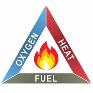
To obtain safe, reliable burner combustion, the above 3 elements must be introduced at the right time and quantity.
For sustained effective and efficient combustion, we follow the Three T’s of time, temperature, and turbulence.
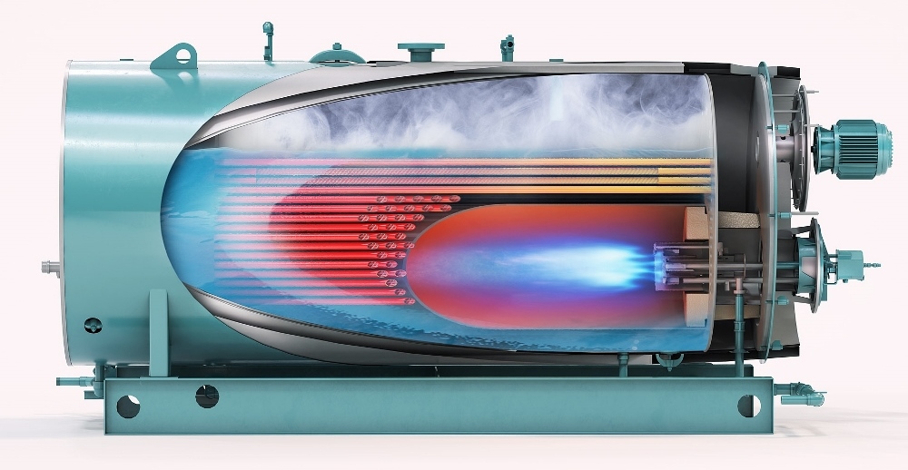
The Time of combustion refers to rate of reaction. Fuel (natural gas, propane etc…), is introduced to the combustion zone as described in the steps below. The volumetric rate is metered by burner architecture via orifices, lances, spuds or other similar means. Size and quantity of these delivery methods result in gas velocity and volume required to achieve rated capacities and limit emissions during the resident time in the main furnace. Air-fuel ratios must be controlled to maintain stable, clean flame geometry within the furnace throughout various firing rates.
The Temperature of combustion is inherent to above attributes. Once we establish the primary or main flame (see sequence below), the heat present will maintain the temperature to continue the chemical reaction.
The Turbulence of combustion comes from the introduction method of fuel with air mixing and is vital to achieving stable and complete combustion. As a result, methods used will help to abate VOCs (volatile organic compounds) including reducing carbon monoxide and nitrogen oxide (NOx) emission. Boiler furnace and refractory design play an important role in turbulence produced to effect an efficient clean flame pattern.
CFD (Computational Fluid Dynamics) modeling is complex process often used to develop a good match between burner & boiler in commercial & Industrial boilers. This complex process will only be mentioned here due to the extensive analysis required for its development.
Example of an Industrial Low NOx burner (NatCom)
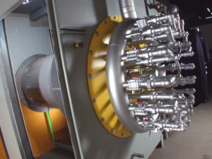
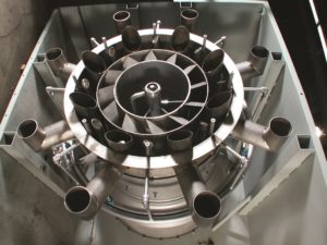
These combustion systems are designed and engineered on our burner-control systems, to meet the most stringent emission requirements mandated to date.
The Following steps outline the burner combustion flame sequence:
Step #1. A call for heat is signaled to the boiler’s flame safeguard (sequence) control. This control starts a combustion air fan (oxygen) which in-turn energizes a pressure switch confirming fan air pressure. The boiler’s burner fan is engineered by the manufacture to produce enough combustion air to fire the burner at its variable, min./max. capacity. The sequence controller initiates an internal timer to “pre-purge” combustion chamber to accomplish a minimum of four (4) complete air changes per code, through combustion chamber and flue passages to flue stack outlet prior to start. This code requirement offers inherent safety by removing residual unburned fuel or in the case of a leaking fuel valve, miniscule amount of fuel in the combustion chamber at light-off so as not to cause an explosive environment resulting in unwanted occurrence.
Step #2. Once timed sequence of pre-purge is complete and all safety parameters met, air dampers are electrically positioned to start.
Note: Some burners often found on condensing boilers include VSD (variable speed drive) fan motors, increasing fan RPM for pre-purge, then decreases to a proper set point for light off to accommodate pilot fuel for light-off.
Step #3. Simultaneously a gas pilot solenoid valve opens, while an ignition transformer energizes spark or glow plug (heat) to ignite pilot (fuel) establishing pilot flame prior to main fuel valve opening.
Step #4. Pilot flame is confirmed via flame rectification (Scanner Cell or Flame Rod) to flame safeguard control where sequence is automatically advanced to allow for main fuel valve(s) to open establishing a low fire in the boiler’s combustion chamber.
Step #5. Once main fuel valve(s) is open and flame signal remains strong, pilot fuel valve and spark or glow plug are de-energized, the flame safeguard control releases burner operation for firing rate /modulation to the respective controller packaged with boiler or from remote signal from a Plant Master or other firing rate type control. Assuming boiler has been properly warmed, modulation control will position firing rate to match boiler load.
Step #6. When steam or hot water load is satisfied and system demand is less than fuel (energy) input by the burner in low fire – minimum firing rate, burner’s flame safeguard control will begin burner shut-down sequence. This process includes a “post-purge” time to eliminate unburned fuel from chamber and flue passages, prior to shut down. At this point the boiler/burner is ready to start the sequence over again upon demand.
Note: The sequence above is very general. There is a lot more going on electronically relative to the combustion process than what is mentioned in this blog.
For more information relative to the variety of products offered as new or retrofit in your existing boiler plant, contact our Sales or Parts department.
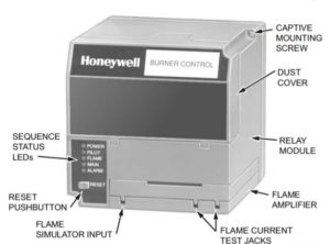
Typical Flame Safeguard Sequence Control
Hope to see you next month for Part 2 of “Combustion”, where we will look at boiler stack draft and different fuels as it relates to combustion.
Information in this blog is being furnished by D. J. Conley Associates Inc. and by those having numerous years of experience in design, installation and application with generation of heating and process steam and hot water products and services. This information, along with supplemental data obtained from a variety of sources, is for the beneficial use of its audience only. We cannot be held liable for the application or misapplication of products or methods associated with this data which may cause unfavorable issues or harmful outcomes. There are many circumstances beyond our control at play in individual systems. You are welcome to contact us in the event questions should arise.