Category

Combustion

Combustion – Part 3

By | Combustion | No Comments

Part 3 of 3 – Flue Gas Stack & Draft

In our final blog series on combustion, we will cover a vital component to proper boiler/burner operation, Stack Draft!

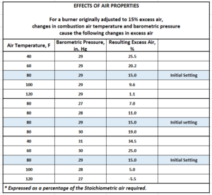
Flue gas draft or “stack effect” is established by the pressure and temperature difference between inside and outside the stack and building. As hotter, less dense gases inside the bottom of the stack rise, draws in cooler, higher (combustion)air pressure. The higher external air pressure moves combustion air into a natural draft burner for the combustion process. Other factors that affect draft are wind fluctuations, chimney height, burner firing rate, air heaters, stack economizers, dampers or other fittings and barometric conditions. The varying conditions are in a constant state of change. To counter these changes, engineers design flue gas systems that take flue stack & breeching size design, layout, burner/boiler type and ancillary equipment into consideration. Varying draft conditions can affect combustion therefore must be understood to provide stable, trouble free combustion within the envelope of mechanical code. Too little or too much draft can create a variety of problems such as poor burner light off, combustion rumbles, varied fuel inputs, pilot failures, stand-by heat losses and could even void equipment warranties if not addressed and corrected.

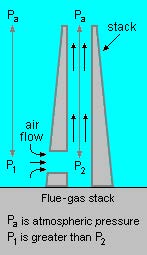
Chimney Stack Effect: See example below.

The absolute air pressure (Pa) to (P1) at boiler/burner entrance and (P2) at boiler/burner exhaust outlet and entrance to stack shows the airflow as the hotter more buoyant air rises indicated with arrows.

Following Describes draft type and how they are controlled:

  • Natural draft: Natural draft in a flue gas stack system is created as described in detail above. Natural Draft Systems can also be controlled by inlet/outlet dampers. Natural draft effect exists in atmospheric, fan assisted and forced draft systems as well.
  • Forced draft: Air and flue gases are maintained by a motor driven fan to produce pressures above atmospheric. The forced draft fan system is normally a jet type or integrated into the boiler/burner design, forcing primary combustion air through a plenum, directing air flow through a diffuser or similar, to mix with fuel flow at set levels creating stable combustion.
  • Induced draft: Air or flue gases flow under the effect of a gradually decreasing pressure below atmospheric pressure. In this case, the system is said to operate under induced draft, the stack or chimney can provide sufficient natural draft to meet the low draft losses. To achieve higher pressure differentials, the stacks must simultaneously operate with draft fans and controls to maintain proper draft setting.
  • Balanced draft: When the static pressure is equal to the atmospheric pressure, the system is referred to as balanced draft. Draft is said to be zero in the system, however, must rely upon accurate controlled FD (Forced Draft) fan and often, ID (Induced Draft) fan and/or damper operation to ensure constant flue gas exit to atmosphere.

Note: Mechanical Draft systems shall be listed in accordance with UL 378, “Draft Equipment” and installed in accordance with both the appliance and the mechanical draft system manufacture’s installation instructions.

With any stack system design, draft must be kept within the manufacturers draft tolerance for safe, trouble free operation.

Design considerations must also factor ancillary products into the equation as previously mentioned such as air heaters, stack economizers, damper, or other fittings along with losses from internal stack surface.

Materials of construction must be considered to match the appliance category for compliance with code and to mitigate premature failure of stack & breeching selected. More on venting categories below.

Very tall individual or combined venting stack systems may require utilizing sequence draft control due to draft variance created in the system from multiple burners and their associated turn-down. Stack heights are dictated by building and mechanical code and/or State mandates during the air permitting process. A draft calculation should accompany all combined venting designs and those beyond a simple short vertical stack or that which is defined in the manufacture’s installation manual.

On large power plants, the required stack height design may include CEM (Continuous Emission Monitoring) systems and/or annual MACT testing to obtain or maintain an operating permit. These mandates can become very costly therefore it is best to understand the potential requirement up front for feasibility and budgeting.

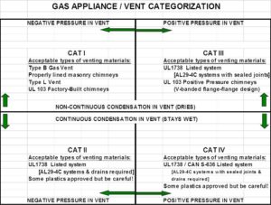
Though this blog centers on combustion, draft being a major component for proper combustion, this is a good place to offer some additional information on draft venting material and use within a boiler system. The following 4 venting categories will provide some insight as to previously mentioned materials of construction for prefabricated and welded or site-built stack systems.  

Category I: Natural Draft (non-pressurized) venting systems serving one or more listed appliances equipped with draft hood or listed for use with Type B gas vent usually residential or commercial appliances installed in the single story of a building and is of the non-condensing type of unit. This can also include “fan-assisted” gas appliances that operate with neutral or negative draft. Stack materials are often single or double wall and made from galvanized or aluminized steel.

Category II:  Category II venting is for a “condensing” appliance that operates with a non-positive (neutral or negative) vent. Stack materials are usually single or double wall with the inner wall made from special stainless steel to avoid corrosion from condensation.

Category III: A non-condensing gas appliance that operates with a positive vent pressure. These are equipped with a forced draft robust burner-blower motor and can normally overcome slight stack system back pressure manufactures instructions. Materials are usually double wall aluminized or stainless steel based on fuel being burned, budget and customer preference.

Category IV:  A condensing gas appliance that operates with a positive vent pressure as listed. Stack materials are usually double wall with inner wall being a special stainless steel to avoid corrosion from condensation.

For more information on stack categories, See illustration below and NFPA 54, ANSI Z223.1 or the International Fuel Gas code (IFGC 2021)

When designing a gas venting system with an “in-line” induced draft fan, keep in mind all stack materials “downstream” of the induced draft fan must comply with Category III or Category IV material accordingly. Also, it must be understood, that though many manufactures allow and list their appliance for use with (code approved) PVC & CPVC venting material, those materials have the inherent danger of being compromised if mechanical, electrical systems or high limit temperature sensor failure occurs. Upon failure, plastic pipe can split or melt resulting in the release of carbon monoxide to occupied areas. Though this may seldom happen, one must question if material & installation cost difference is worth the risk. We recommend using all non-combustible metals, stainless steel and/or stainless lined refractory stacks to avoid this potential.

Draft & Barometric Dampers:  Barometric dampers on stack and breeching systems are often used to address excessive draft conditions in category 1 venting by using a counter-balance blade-type damper, normally installed at the base of the stack or far end of the breeching.

These types of damper arrangements are limited by code, however, many stack and breeching systems that were originally designed into Category III and IV appliance systems were either grandfathered due to age, or permission granted by local jurisdiction where other systems would simply not work. Before implementing a barometric damper into a stack system, make certain to obtain approval from the boiler manufacture, engineer and local inspector having jurisdiction over the installation. Some installations may require a carbon monoxide detection and alarm system to ensure safe shut-down w/alarm in case of damper spillage.

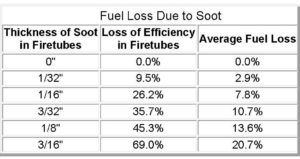
In summary: boiler/burner combustion can be complicated. It is best to understand design intent, application, installation, code requirements and equipment specifications prior to setting or trouble shooting combustion. Linkage, servos, manual and automatic gas valves, regulators, gaskets, seals, insulating materials, refractory, diffusers, gas housings and ports all play an important role in solid repeatable combustion along with a well-designed venting system and can provide 30 plus years of reliable service to an owner. Final thought regarding burner tune-ups and maintaining proper combustion; if your burner’s air-fuel ratio is too lean, un-stable combustion & efficiency loss from high excess air levels can be expected; if too rich, not only can you “overheat” boiler metals, heads, flanges, gaskets, and insulating materials to the point of costly repairs, risk the loss of efficiency and face expensive clean-up from soot deposits on the fireside and stack system.

See chart below for an example of potential energy loss due to soot build-up in a boiler.

Other resources: Guide for Boiler Tune-Up can be found here:

https://www.epa.gov/sites/production/files/2016-09/documents/tune-up_guide.pdf

We hope you found this quick journey through Boiler-Burner combustion & draft informative and useful.

Please drop us a line if you wish to learn more. Our expert Sales & Service Specialists are here to assist you in the design, application and troubleshooting of new and existing boiler/burners, Low NOx burners & controls, engine exhaust, commercial/industrial laundry, coffee roasters and pizza ovens.   

We hope to see you back in our next blog when we take a closer look at burners and burner Control Systems.

Information in this blog is being furnished by D. J. Conley Associates Inc. and by those having numerous years of experience in design, installation, and application with generation of heating and process steam and hot water products and services. This information along with supplemental data obtained from a variety of sources is for the beneficial use of its audience only. We cannot be held liable for the application or misapplication of products or methods associated with this data which may cause unfavorable issues or harmful outcomes since there are many circumstances beyond our control at play in every individual system. You are welcome to contact us in the event questions should arise.

Combustion – Part 2

By | Combustion

PART 2 of 3 –  Fuels, Setting, Adjustment & Testing

FUELS

The combustion process of converting fuel to energy, not as popular as the international push toward carbon neutrality and emission reduction, still remain a vital force in producing steam and hot water via conventional and hybrid burners. Common fuels such as natural gas & propane come standard on most new boiler/burner systems. Alternate fuels such as bio-fuels, land-fill gas, methane from waste treatment facilities and ethanol from corn can be burned as primary, secondary or simultaneous fired configurations in some conventional boilers. Bio-mass fuels such as wood pellets, briquettes or logs and other raw materials are also used to fuel boilers.  Gas fired boiler/burners, light fuel oils such as kerosene, #2 fuel oil and in some cases heavier oils which must be heated prior to use are often used as a reliable back-up fuel source. The above alternative liquid fuels come with more stringent regulation.  They are most notably selected as back-up fuel at critical care facilities such as hospitals or in remote areas where other gaseous or alternate fuels and not readily available or too costly deliver. Alternative fuels, solid (bio-mass) or liquid used today require a special permitting process. Though all states are governed by the U.S. EPA Federal Register’s latest version of 40 CFR. each state may have additional regulations as well. The idea is that replacement commercial & Industrial boilers with fuel burners, along with other larger fuel burning equipment such as kilns, incinerators and other industrial burn processes, are less polluting than previous versions.

In Michigan, these and other added sources require prior approval from the Michigan DEQ/EGLE, (Department of Environment, Great Lakes & Energy), AQD (Air Quality Division) who have been given authority by U.S. EPA to govern the permitting process.

You can navigate this complex process regarding NESHAP (National Emission Standard for Hazardous Air Pollutants) otherwise known as Boiler MACT (maximum achievable controls technology), by following this link:

https://www.michigan.gov/egle/0,9429,7-135-3310-262365–,00.html

Application must be submitted prior to procurement and follow the NSPS (new source performance standards).  To learn more from the U.S EPA, follow this link:

 https://www.energy.gov/eere/amo/boiler-mact

There exists a plethora of rabbit trails to continue down with regards to emissions, though not the intent of this blog.  

If you should have a need to explore the use of any of these fuel options mentioned, please contact our sales professionals who can assist you in system design and selection of the right burner/boiler combination for your facility.  

The Importance of Settings, Adjustments & Testing

Air properties change with air temperature and barometric pressure which directly effects the combustion process. 

To operate your boiler’s burner at optimal efficiency, settings should be made to coincide with these atmospheric changes. On larger commercial and Industrial boilers, minor corrections to combustion settings to maintain constant fuel-air ratios can result in fuel savings to the owner. See “Effects of Air Properties” chart below. Typical excess air levels are set at 15% during the start of a new boiler or at the beginning of a heating season. 

Notice the change in excess air levels as the temperature or barometric pressure changes. With a “decrease” in air temperature from original set point, and without any corrective adjustment, excess air climbs resulting in inefficient combustion and wasted fuel.

Conversely an “Increase” in air temperature can greatly reduce excess air and not only render the burner inefficient, but if left uncorrected, can build carbon on the fireside of your heat exchanger.  This can lead to extreme loss of efficiency and possible damage to other components that overheated since proper heat transfer could not take place in the exchanger. The reverse occurs with barometric pressure changes, but with similar results.  

Further, in traditional burners, linkage assemblies can have inherent slippage and wear, (hysteresis) causing poor repeatability to fuel-air characterized inputs.

One solution is to upgrade your burner with direct, “Servo” type actuators on fuel butterfly and air damper(s) and can also include a flue-gas recirculation damper on Low NOx burners. New controls and drive units will greatly improve repeatability, improve emissions, and stabilize inputs by reducing linkage hysteresis and achieve constant burner air-fuel ratios.

Keep in mind, the above-mentioned air property effects remain in-play after converting to direct drive controller. This can be addressed by implementing an oxygen trim system. Oxygen trim systems include an oxygen cell (Zirconium Oxide) which constantly samples the exiting flue gases to provide electronic feedback signal to control logic.  The controller then sends a corrective signal to “trim” (very slight adjustment) a drive servo, either air or fuel, bringing combustion back in line with original set point for peak efficiency.

Note: Oxygen trim systems do require periodic testing of the oxygen cells to make certain they have not been fowled, deteriorated, or compromised rendering them ineffective.  Cell replacement can be costly. Check with your supplier on recommended replacement intervals and costs to maintain an Oxygen Trim system prior to purchase to ensure your ROI is beneficial with fuel and maintenance savings. Also, your energy provider may offer incentives in the form of rebates to have certain fuel saving technologies installed.   

If you want more information about periodic combustion testing, fuel savings, energy rebates, combustion setting or wish to obtain information on upgrading your current burner equipment, please contact our office’s Aftermarket Services department for assistance.

Settings, Adjustment & Testing

It is often said that combustion setting is both an “ART” and a science, applying both equally to obtain the best possible outcome when setting combustion on a complex burner. Combustion setting should ALWAYS be done by trained professionals with a full understanding of the variables associated with each individual burner, as well the mechanics, electronics, chemical reaction of fuels and air producing the exothermic reaction resulted by these settings.

Burner technicians use a stack gas analyzer while making burner adjustments for clean, efficient combustion. Adjustments normally take place when the boiler is up to normal operating pressure and temperature since a hot furnace will create different combustion results than a cold furnace. In addition, it is good practice to view flame pattern via sight glass at the back of the boiler to ensure there is no flame impingement and that refractory or insulating material integrity exists.

This is what that process might look like:

  • Read and understand the manufactures recommended procedures, setting and operating instructions for the specific burner to be set. 
  • Make certain to have tools necessary for adjustments, including but not limited to, special wrenches, lubricants (if required), pressure and temperature gauges with ranges to match burner requirements, laptop, or other computing device as necessary, access to platforms/ladders if required to reach flue gas outlet port and a calibrated combustion analyzer for certified results.

Hand-Held Combustion Analyzer


Advanced Combustion Analyzer

  • Adjustment Variables: Understand variables associated with the process of combustion such as the fuel delivery system, gas or oil pressures available, economizer and assuring the venting is clear (more on venting and draft in Part 3). 
    • Adequate Combustion Air: To assure adequate combustion air is available, check louvres and combustion air interlocks for proper operation. If “sealed combustion” via direct duct from outdoor to boiler/burner is used, filters or mesh intake should be free of dirt, dust, lint, or debris such as bird nests & spider webs.  
    • Boiler Load: When preparing to perform combustion setting and/or testing, a boiler load should be available or another way to disperse generated heat, to avoid auto shut down if set points are quickly reached most likely during higher firing rates.
    • Adjusting Combustion: When adjusting combustion at low fire with linkage or servo-driven equipment, test fire the burner multiple times after low fire adjustments to ensure excess air has not adversely affected the pilot light-off setting.
  •  
  • Standard Linkage System

Servo-Drive Air-Fuel System

Gas Meter: During initial combustion setting at high fire on gas, make certain to clock the gas meter. Pressure and/or temperature correction factors must be applied to your input readings. Necessary changes must be made to compensate for accuracy before proceeding, then final readings should be recorded on report.

  • Overfire or Low Fire: Most manufactures provide combustion air fans that will produce significant overfire air for safety reasons, however this can allow “overfiring” a boiler resulting in damage if not caught and corrected by accurate fuel meter input readings. Gas meter readings at low fire are also important so burner’s turn-down ratio design is not exceeded.
  • Final Adjustment: Tighten and/or lock all linkages, set-screws, brackets etc. after final adjustment is made and record set points. Linkage can be marked and photos taken to illustrate how burner settings were finalized.
  • Recording and Reporting: Record all settings on proper forms which include blocks for all readings in harmony with type of adjustments the owner requested. For example if simple “testing” with no adjustments, a basic combustion form can be used. If customer requires more stringent MACT type testing, then advanced forms must be used to outline procedures and include advanced details not normally required for owner’s submittal process.

Some newer burners operate on the “zero-governor” principle requiring minor or no seasonal adjustment to fuel valve setting since air will aspirate with fuel on a 1:1 basis. As air temperature & pressure changes, fuel increases or decreases accordingly.

During the process of combustion “testing-only” readings (O2, CO & Co2) outside acceptable manufacture parameters require investigation. Return burner to low fire position then shut down. Lock-out, tag-out burner’s electrical feed and notify the customer for adjusting approval. Do not re-employ a burner that is out of adjustment without proper correction and recording.

Sample of a combustion form:

For further information or if you have need for setting and testing combustion on your boiler, please contact your service provider for assistance.

Hope to see you next month for Part 3 of “Combustion”, covering boiler/burner flue stack & draft.

Information in this blog is furnished by D. J. Conley Associates Inc. and by those having numerous years of experience in design, installation, and application with generation of heating and process steam and hot water products and services. This information along with supplemental data obtained from a variety of sources is for the beneficial use of its audience only. We cannot be held liable for the application or misapplication of products or methods associated with this data which may cause unfavorable issues or harmful outcomes since there are many circumstances beyond our control at play in every individual system. You are welcome to contact us in the event questions should arise.


Combustion – Part 1

By | Combustion

PART 1 OF 3

Greetings and Welcome back to our blog series!

In keeping with world events this past year, we would like to present our version of volatility better known as the process of combustion in conventional boilers. The goal is to take you on a short journey through the basic concept of combustion including its process, application, effects, fuels, along with sequence of operation, checking (testing) & setting combustion as related to commercial & industrial boilers. So let’s fire it up!

We will first review basic process as we begin to better understand safe-reliable burner combustion in a boiler. Chances are you benefit from the combustion process in your daily life, driving an automobile, cooking, heating your home or a variety of other ways. You were likely exposed at an early age to the direct process of combustion watching your folks build a campfire or playing with blue-tip stick matches to ignite your favorite tobacco, experimenting with alcohol lamps or Bunsen burners in a school lab. Combustion is all around us.

There are three basic components that must be present in combustion for this chemical reaction to take place.

  1. Oxygen
  2. Fuel
  3. Heat (spark or other means)

Better illustrated by the common triangle shown below.

To obtain safe, reliable burner combustion, the above 3 elements must be introduced at the right time and quantity.

For sustained effective and efficient combustion, we follow the Three T’s of time, temperature, and turbulence.

The Time of combustion refers to rate of reaction. Fuel (natural gas, propane etc…), is introduced to the combustion zone as described in the steps below. The volumetric rate is metered by burner architecture via orifices, lances, spuds or other similar means. Size and quantity of these delivery methods result in gas velocity and volume required to achieve rated capacities and limit emissions during the resident time in the main furnace.  Air-fuel ratios must be controlled to maintain stable, clean flame geometry within the furnace throughout various firing rates.

The Temperature of combustion is inherent to above attributes. Once we establish the primary or main flame (see sequence below), the heat present will maintain the temperature to continue the chemical reaction.

The Turbulence of combustion comes from the introduction method of fuel with air mixing and is vital to achieving stable and complete combustion. As a result, methods used will help to abate VOCs (volatile organic compounds) including  reducing carbon monoxide and nitrogen oxide (NOx) emission. Boiler furnace and refractory design play an important role in turbulence produced to effect an efficient clean flame pattern.

CFD (Computational Fluid Dynamics) modeling is complex process often used to develop a good match between burner & boiler in commercial & Industrial boilers. This complex process will only be mentioned here due to the extensive analysis required for its development.

Example of an Industrial Low NOx burner (NatCom)


These combustion systems are designed and engineered on our burner-control systems, to meet the most stringent emission requirements mandated to date.

The Following steps outline the burner combustion flame sequence:

Step #1. A call for heat is signaled to the boiler’s flame safeguard (sequence) control. This control starts a combustion air fan (oxygen) which in-turn energizes a pressure switch confirming fan air pressure. The boiler’s burner fan is engineered by the manufacture to produce enough combustion air to fire the burner at its variable, min./max. capacity. The sequence controller initiates an internal timer to “pre-purge” combustion chamber to accomplish a minimum of four (4) complete air changes per code, through combustion chamber and flue passages to flue stack outlet prior to start. This code requirement offers inherent safety by removing residual unburned fuel or in the case of a leaking fuel valve, miniscule amount of fuel in the combustion chamber at light-off so as not to cause an explosive environment resulting in unwanted occurrence.

Step #2.  Once timed sequence of pre-purge is complete and all safety parameters met, air dampers are electrically positioned to start.

Note: Some burners often found on condensing boilers include VSD (variable speed drive) fan motors, increasing fan RPM for pre-purge, then decreases to a proper set point for light off to accommodate pilot fuel for light-off.

Step #3. Simultaneously a gas pilot solenoid valve opens, while an ignition transformer energizes spark or glow plug (heat) to ignite pilot (fuel) establishing pilot flame prior to main fuel valve opening.

Step #4. Pilot flame is confirmed via flame rectification (Scanner Cell or Flame Rod) to flame safeguard control where sequence is automatically advanced to allow for main fuel valve(s) to open establishing a low fire in the boiler’s combustion chamber.

Step #5. Once main fuel valve(s) is open and flame signal remains strong, pilot fuel valve and spark or glow plug are de-energized, the flame safeguard control releases burner operation for firing rate /modulation to the respective controller packaged with boiler or from remote signal from a Plant Master or other firing rate type control. Assuming boiler has been properly warmed, modulation control will position firing rate to match boiler load.

Step #6. When steam or hot water load is satisfied and system demand is less than fuel (energy) input by the burner in low fire – minimum firing rate, burner’s flame safeguard control will begin burner shut-down sequence. This process includes a “post-purge” time to eliminate unburned fuel from chamber and flue passages, prior to shut down. At this point the boiler/burner is ready to start the sequence over again upon demand.

Note: The sequence above is very general. There is a lot more going on electronically relative to the combustion process than what is mentioned in this blog.

For more information relative to the variety of products offered as new or retrofit in your existing boiler plant, contact our Sales or Parts department.

Typical Flame Safeguard Sequence Control

Hope to see you next month for Part 2 of “Combustion”, where we will look at boiler stack draft and different fuels as it relates to combustion.

 Information in this blog is being furnished by D. J. Conley Associates Inc. and by those having numerous years of experience in design, installation and application with generation of heating and process steam and hot water products and services. This information, along with supplemental data obtained from a variety of sources, is for the beneficial use of its audience only. We cannot be held liable for the application or misapplication of products or methods associated with this data which may cause unfavorable issues or harmful outcomes. There are many circumstances beyond our control at play in individual systems. You are welcome to contact us in the event questions should arise.