Part 3 of 3 – Flue Gas Stack & Draft
In our final blog series on combustion, we will cover a vital component to proper boiler/burner operation, Stack Draft!
Flue gas draft or “stack effect” is established by the pressure and temperature difference between inside and outside the stack and building. As hotter, less dense gases inside the bottom of the stack rise, draws in cooler, higher (combustion)air pressure. The higher external air pressure moves combustion air into a natural draft burner for the combustion process. Other factors that affect draft are wind fluctuations, chimney height, burner firing rate, air heaters, stack economizers, dampers or other fittings and barometric conditions. The varying conditions are in a constant state of change. To counter these changes, engineers design flue gas systems that take flue stack & breeching size design, layout, burner/boiler type and ancillary equipment into consideration. Varying draft conditions can affect combustion therefore must be understood to provide stable, trouble free combustion within the envelope of mechanical code. Too little or too much draft can create a variety of problems such as poor burner light off, combustion rumbles, varied fuel inputs, pilot failures, stand-by heat losses and could even void equipment warranties if not addressed and corrected.
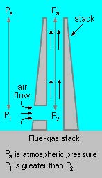
Chimney Stack Effect: See example below.
The absolute air pressure (Pa) to (P1) at boiler/burner entrance and (P2) at boiler/burner exhaust outlet and entrance to stack shows the airflow as the hotter more buoyant air rises indicated with arrows.

Following Describes draft type and how they are controlled:
- Natural draft: Natural draft in a flue gas stack system is created as described in detail above. Natural Draft Systems can also be controlled by inlet/outlet dampers. Natural draft effect exists in atmospheric, fan assisted and forced draft systems as well.
- Forced draft: Air and flue gases are maintained by a motor driven fan to produce pressures above atmospheric. The forced draft fan system is normally a jet type or integrated into the boiler/burner design, forcing primary combustion air through a plenum, directing air flow through a diffuser or similar, to mix with fuel flow at set levels creating stable combustion.
- Induced draft: Air or flue gases flow under the effect of a gradually decreasing pressure below atmospheric pressure. In this case, the system is said to operate under induced draft, the stack or chimney can provide sufficient natural draft to meet the low draft losses. To achieve higher pressure differentials, the stacks must simultaneously operate with draft fans and controls to maintain proper draft setting.
- Balanced draft: When the static pressure is equal to the atmospheric pressure, the system is referred to as balanced draft. Draft is said to be zero in the system, however, must rely upon accurate controlled FD (Forced Draft) fan and often, ID (Induced Draft) fan and/or damper operation to ensure constant flue gas exit to atmosphere.
Note: Mechanical Draft systems shall be listed in accordance with UL 378, “Draft Equipment” and installed in accordance with both the appliance and the mechanical draft system manufacture’s installation instructions.
With any stack system design, draft must be kept within the manufacturers draft tolerance for safe, trouble free operation.
Design considerations must also factor ancillary products into the equation as previously mentioned such as air heaters, stack economizers, damper, or other fittings along with losses from internal stack surface.
Materials of construction must be considered to match the appliance category for compliance with code and to mitigate premature failure of stack & breeching selected. More on venting categories below.
Very tall individual or combined venting stack systems may require utilizing sequence draft control due to draft variance created in the system from multiple burners and their associated turn-down. Stack heights are dictated by building and mechanical code and/or State mandates during the air permitting process. A draft calculation should accompany all combined venting designs and those beyond a simple short vertical stack or that which is defined in the manufacture’s installation manual.
On large power plants, the required stack height design may include CEM (Continuous Emission Monitoring) systems and/or annual MACT testing to obtain or maintain an operating permit. These mandates can become very costly therefore it is best to understand the potential requirement up front for feasibility and budgeting.
Though this blog centers on combustion, draft being a major component for proper combustion, this is a good place to offer some additional information on draft venting material and use within a boiler system. The following 4 venting categories will provide some insight as to previously mentioned materials of construction for prefabricated and welded or site-built stack systems.
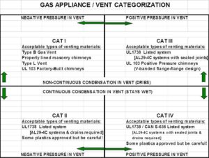
Category I: Natural Draft (non-pressurized) venting systems serving one or more listed appliances equipped with draft hood or listed for use with Type B gas vent usually residential or commercial appliances installed in the single story of a building and is of the non-condensing type of unit. This can also include “fan-assisted” gas appliances that operate with neutral or negative draft. Stack materials are often single or double wall and made from galvanized or aluminized steel.
Category II: Category II venting is for a “condensing” appliance that operates with a non-positive (neutral or negative) vent. Stack materials are usually single or double wall with the inner wall made from special stainless steel to avoid corrosion from condensation.
Category III: A non-condensing gas appliance that operates with a positive vent pressure. These are equipped with a forced draft robust burner-blower motor and can normally overcome slight stack system back pressure manufactures instructions. Materials are usually double wall aluminized or stainless steel based on fuel being burned, budget and customer preference.
Category IV: A condensing gas appliance that operates with a positive vent pressure as listed. Stack materials are usually double wall with inner wall being a special stainless steel to avoid corrosion from condensation.
For more information on stack categories, See illustration below and NFPA 54, ANSI Z223.1 or the International Fuel Gas code (IFGC 2021)

When designing a gas venting system with an “in-line” induced draft fan, keep in mind all stack materials “downstream” of the induced draft fan must comply with Category III or Category IV material accordingly. Also, it must be understood, that though many manufactures allow and list their appliance for use with (code approved) PVC & CPVC venting material, those materials have the inherent danger of being compromised if mechanical, electrical systems or high limit temperature sensor failure occurs. Upon failure, plastic pipe can split or melt resulting in the release of carbon monoxide to occupied areas. Though this may seldom happen, one must question if material & installation cost difference is worth the risk. We recommend using all non-combustible metals, stainless steel and/or stainless lined refractory stacks to avoid this potential.
Draft & Barometric Dampers: Barometric dampers on stack and breeching systems are often used to address excessive draft conditions in category 1 venting by using a counter-balance blade-type damper, normally installed at the base of the stack or far end of the breeching.
These types of damper arrangements are limited by code, however, many stack and breeching systems that were originally designed into Category III and IV appliance systems were either grandfathered due to age, or permission granted by local jurisdiction where other systems would simply not work. Before implementing a barometric damper into a stack system, make certain to obtain approval from the boiler manufacture, engineer and local inspector having jurisdiction over the installation. Some installations may require a carbon monoxide detection and alarm system to ensure safe shut-down w/alarm in case of damper spillage.
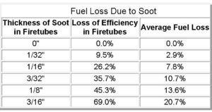
In summary: boiler/burner combustion can be complicated. It is best to understand design intent, application, installation, code requirements and equipment specifications prior to setting or trouble shooting combustion. Linkage, servos, manual and automatic gas valves, regulators, gaskets, seals, insulating materials, refractory, diffusers, gas housings and ports all play an important role in solid repeatable combustion along with a well-designed venting system and can provide 30 plus years of reliable service to an owner. Final thought regarding burner tune-ups and maintaining proper combustion; if your burner’s air-fuel ratio is too lean, un-stable combustion & efficiency loss from high excess air levels can be expected; if too rich, not only can you “overheat” boiler metals, heads, flanges, gaskets, and insulating materials to the point of costly repairs, risk the loss of efficiency and face expensive clean-up from soot deposits on the fireside and stack system.
See chart below for an example of potential energy loss due to soot build-up in a boiler.

Other resources: Guide for Boiler Tune-Up can be found here:
https://www.epa.gov/sites/production/files/2016-09/documents/tune-up_guide.pdf
We hope you found this quick journey through Boiler-Burner combustion & draft informative and useful.
Please drop us a line if you wish to learn more. Our expert Sales & Service Specialists are here to assist you in the design, application and troubleshooting of new and existing boiler/burners, Low NOx burners & controls, engine exhaust, commercial/industrial laundry, coffee roasters and pizza ovens.
We hope to see you back in our next blog when we take a closer look at burners and burner Control Systems.
Information in this blog is being furnished by D. J. Conley Associates Inc. and by those having numerous years of experience in design, installation, and application with generation of heating and process steam and hot water products and services. This information along with supplemental data obtained from a variety of sources is for the beneficial use of its audience only. We cannot be held liable for the application or misapplication of products or methods associated with this data which may cause unfavorable issues or harmful outcomes since there are many circumstances beyond our control at play in every individual system. You are welcome to contact us in the event questions should arise.
